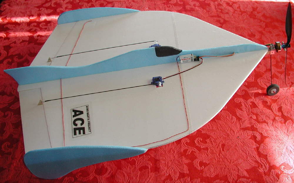
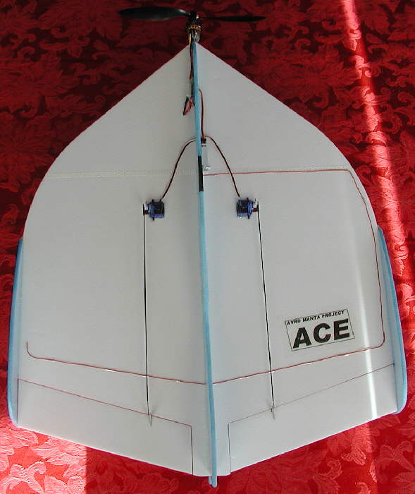
This "ACE" is my own design approach, drawing on all of the prior inspirations of my work on the MANTA RC design, along with my own aircraft design perspectives and understandings. The 'Fantasy Scale" fuselage is a new aspect of this design, as is the underside forward battery compartment and utterly simple landing gear implementation.
The ACE is likely the easiest-building aircraft I've designed to date... and it flies superbly! You may want to build one for yourself! I'll provide enough in the way of plans and instructions so you should be able to do that. The base design criteria is to KEEP IT LIGHT & SIMPLE!
This just might also be one of the best candidates for setting up as a night flying LED lighted "UFO" type design. I'll write up the information for doing that, drawing power from the receiver's unused rudder channel output, as time allows. (I may also design a lightweight mono-ski for flying from & landing on softer snow, that will mount on the simple front landing gear.)
MATERIALS & EQUIPMENT
The entire structure can be built from 1 sheet of DOW Bluecor, Depron, or another RC foam material you have on hand or have access to. I'll be showing photos of the build using a light 6mm foam board with plastic surface film on top & bottom surfaces, which has enough rigidity to not require hard (CF / bamboo, etc.) cross-wing spars
You do need a radio system that has elevon/ delta mixing capability. (Having exponential rates is also very helpful for easy smooth flying.)
The ACE uses an inexpensive 24 gram brushless motor, 12 Amp brushless ESC, and a modest priced 2S 900 mAH LiPoly battery. It also uses a lightweight 4 channel receiver and two inexpensive "5 gram" (to 9 gram) servos. www.Lazertoyz.com is one source within the U.S. which offers decent prices and fast shipping on most of the power system items.
I use 1.5mm CF rods for the elevon linkages with 1/32" music wire ends.
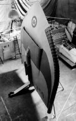
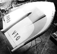
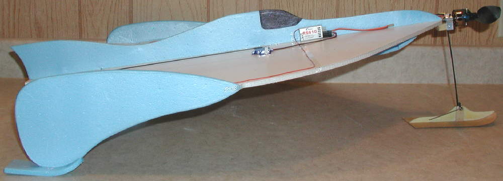
On the Manta "ACE", instead of working on a 'scale' design, I've chosen instead to design a high stability aircraft with large wing tip plates that work not only as vertical stabilizers, but also work as dual wide stance tail skids in conjunction with the single forward wheel, to provide excellent ground handling for both takeoffs and landings. This also offers excellent protection for the propeller and motor.
The elevons are sized nicely to provide excellent control. The upper and lower profile fuselages were designed to both add to the visual impression of a "UFO" inspired craft, as well as to contribute to the structural stiffness in the longitudinal direction.
After having the second Manta Omega prototype come in at a flying weight of 11-3/8 ounces, I decided to use the extended pointed nose profile on this rendition of the ACE to allow the builder to have the lightweight motor farther forward from the ideal CG point, and to have more room between the motor and the CG point to move the battery forward and back to easily achieve balance.
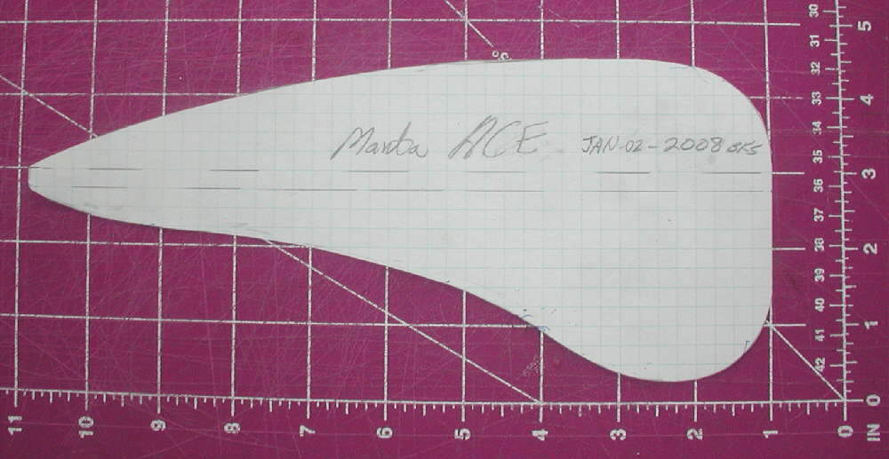
The wing is made from a single layer of 6mm foam; I built this prototype from material which was supplied in a 19-1/8" x 25" sheet (purchased from BPHobbies back in 2006.) It has a white foam core with a plastic surface film on both top and bottom. It is lightweight yet strong, and has enough rigidity so that no span-wise spars were required. Scotch brand cross-filament nylon filament tape was used spareingly in a couple of locations to add what strength is required. Bluecor PP could also be used if desired, or Depron, or possibly other materials; but the underlying emphasis on this design is to keep it light so that it can perform at very slow flying speeds.
On 2S LiPoly batteries, I'm initially very happy with the performance when flying with a GWS 9x4.7 Slow Flyer propeller.
The flight performance, stability, and the aerobatic handling are beyond design expectations; it's a smooth flyer from the rollout and takeoff to the very slow and managable landings. The rolls are very axial. The ACE can be flown nicely in a very limited amount of space, so it should work very well as an indoor flyer.
Using a 10x3.8 prop might also allow irreverently slow maneuvering while maintaining excellent thrust in indoor & outdoor slow flying situations. Conversely, changing to an 8x5 or 8x6 propeller should kick up the top speed, and the roll rate as well. Theswe options will be tested as time allows
While the total wing surface area is similar to that of the 'Manta Omega' designs, the ACE is built at 2/3 of the weight / wing loading. This results in an aircraft that handles superbly at low speeds in a limited amount of airspace. It's incredibly stable, yet responsive.
The Manta ACE would be an *Excellent* night flyer- it's that stable and predictable! I'll add information on the added light systems if & when I add them to this design.
More information, and some basic plans and build sequence notes will be added soon as time allows.
Keeping this build simple was a priority, and it's really a quick and simple build.


You really don't need a 'plan' for the main wing panel. Start directly with a sheet of foam.
(Above) I started with a sheet of foam that was 19-1/8" wide by 25" long, cut 9-1/2" x 9-1/2" triangles off the front corners, and 9" wide by 2-3/4" long triangles off the rear corners. I then rounded the forward wing 'shoulders', then cut in the elevons. The elevon leading edges are beveled for top tape hinging. I use 3/4" wide Scotch transparent 'multipurpose' tape, on both top and bottom, for this purpose.

(Above & Below) Next, I made up the motor mount. I'm using the aluminum stick mount for my 24 gram 'Blue Wonder' motor, and 6" of the heavy / square end of a bamboo chopstick for the main motor mount shaft. I used a 3/4" long piece of 10mm square stick as a spacer to fill out the motor mount, and notched it out to fit the bamboo chopstick. These were glued together before being fit into the motor mount. Last, two small screws were used to lock the motor mount on the stick.
Before doing any assembly / gluing, I marked out the center 1/4" (6mm) wide area on top & bottom where the motor mount and top and bottom fuselage pieces would be mounted. Next, rather than trying to cut and strip away the plastic surface film in this area (which would possibly weaken the structural strength of this sheet foam) I 'woodpeckered' holes in the area so that the glue would penetrate into the foam core and bond solidly.
With the motor mounted in the motor mount and the wires from the motor lashed down with thread and CyA glue to keep them from flexing and breaking during flight, I then mounted the motor mount stick in place on the wing's lower surface with 5 minute epoxy glue. (This is a 0-0 setup- no offset thrust lines, and with the motor mounted as close to the wing panel's center line as the mount allows.)
The wing tip plates were made next; after cutting to size, the edges were heat-formed and tempered using a covering iron set at about 340 degrees. This strengthens the edges of the foam- and is especially nice to do in the lower edges that run on the ground when taking off & landing. (Nylon filament tape could be added for even greater wear resistance along the lower edge that contacts the ground.)
The Balance point / CG is at 9-5/8" back from the front edge of the 25" long foam panel. mark this line at the center, top & bottom, for use when deciding where to place the battery for proper balance.
I next cut a strip of nylon filament tape about 5/16" wide, to run full span (cross-wise) at the balance point location on the top and wrap the edges of the wing panel, then another strip run full span on the bottom, again overlapping the tape from the top at the edges. (This is all the reinfourcing that the wing panel material I used needed. If you are using FFF single surfaced 'protection board', you may want to do more to stiffen the wing laterally.)
Next, I cut two strips of nylon filament tape just the width of the foam wing panel's thickness (6mm) and laid each starting around the nose (just over the motor mount stick), and extending along the edges back to attach onto the front ends of the wing tip plates about 3/4" on each side. This makes the leading edge very durable, while adding only a modest amount of weight.
The top and bottom fuselage pieces were cut from Bluecor PP, starting with strips 2-1/8" wide and 26" long. I then free-handed the top contour to a pleasing flowing contour, starting the rise up to the 'canopy' section about at the balance point. The forward upper section is 1" high. This is a 'stylized' fuselage design, rather than any attempt to be a scale representation of any given John Frost published design... 'artistic license' came into play here! The idea is to add some lengthwise rigidity to the wing panel, without using any heavier material or added bamboo or CF rods.
After the top fuselage piece was shaped in a pleasing manner, I duplicated it for the bottom. then I temporarily held it in place to mark where the rear end of the bamboo chopstick ends, and cut off the forward portion to form the battery compartment. I duplicated this forward cut off piece, so I would have matching side panels for the battery mount area.

[Above:] The mono-wheel landing gear leg is made from a single piece of music wire; A hole sized to match is drilled through both the motor mount and the motor mount stick, stopping againast the inside of the aluminum inner surface of the motor mount. The gear leg is then simply glued into the hole with thin CyA glue. (Note: I first tried a CF rod, which worked OK for quite a few flights, but it eventually hit a piece of frozen-down ice on landing, breaking the CF rod.... so I drilled it out & replaced it with music wire, which works great.)
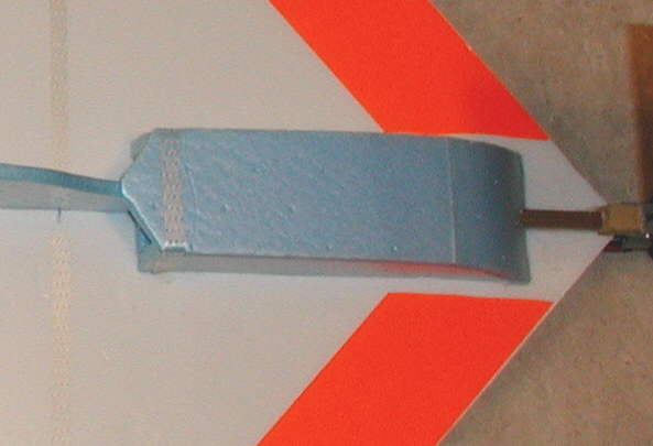
{Above:] These photos show the enclosed battery compartment, with it's tape-hinged cover.
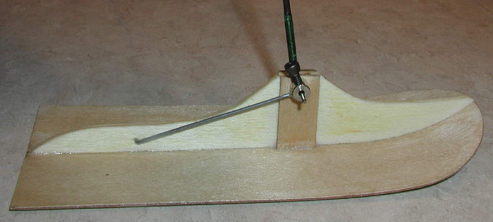
[Above:] Here's a closer look at the ski. It's made from a 1/32" birch plywood, with a lite ply center spine which has 1/16" birch ply doublers where the axle goes through the top. The torque rod is built with music wire soldered into a matching sized hole in the 1/16" brass wheel colar.
[More soon]