
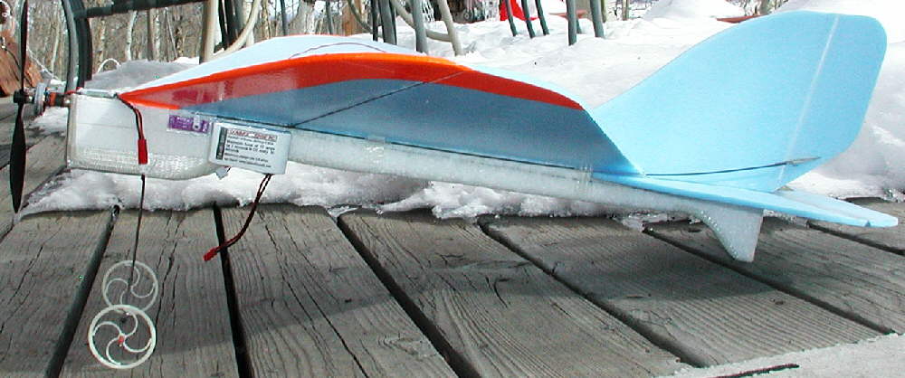
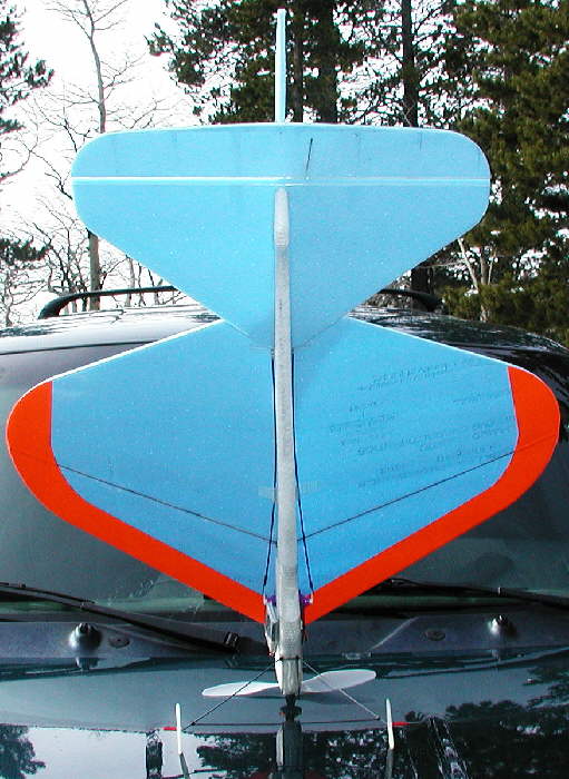
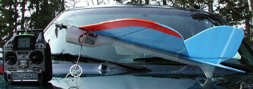
The motor is a GoBrushless GBv kit motor with 23 wraps of 26 gauge wire, Y termination, driven by a Castle Creations Thunderbird 9 ESC. For outdoor flying, I'm using a 9x7 GWS slowflyer prop, which provides almost unlimited vertical, and the ability to do high-alpha maneuvers. Handling is responsive, but very predictable; it'll take off, turn, and land in the same place on the snowpacked road behind me in the photo above!
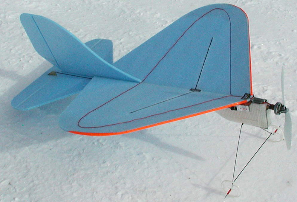
I guess it's time to intruduce you to "CURVACIOUS" - [or "CURVY" for short.] She's a cousin of the Dart family, but with some pleasing curvy lines... and she's really a Sweetheart in the air- always ready for a good time on a moment's notice! (She's always ready to make the most of a cozy flying site, and would be just as happy doing her thing indoors as out!)
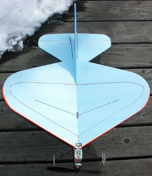
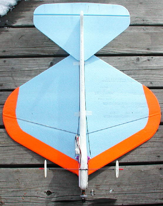
CURVACIOUS has an EPP underbody, and a bluecor wing that's 23-1/2" span, and 18" maximum chord. Power is provided by a 23 wrap [Y] GBv motor turning a 9x7 GWS slowflyer prop on a 2S 800 mAH CSRC LiPoly pack; (Other lighter packs were not performing as well in the cold Colorado New Year's Day flying conditions.)
CURVY is quick to respond to requests, quite nimble for a R-E design, yet predictable in close & down low, and while landing. I'm sure she acts very similar to her cousins in this respect.
(With the big 9x7 prop, it's best to carry some power on landings for smooth touchdowns... that's an impressive drag brake hanging on her nose when that prop stops turning!)

CURVACIOUS sits high on the landing gear for good prop clearance above snow; A GWS 9x7 slow flyer prop was used for outdoor flying; a 10x4.7 prop might perform well on this 23 wind motor for indoor flying . (The axles on the landing gear were left extra long so that EPP foam skis could be completed and mounted later.)
Without the landing gear and flying with a 2S 480mAH LiPoly battery, it can be in the air at 6 ounces for indoor flying. (It was lighter before all of the tape work!) After adding additional Scotch 'Extreme' cross-filament tape, & with the landing gear installed and with my heavier 2S 800 mAH CSRC Lipoly pack for high performance outdoor flying, it's tipping the scales at 7-7/8 ounces.
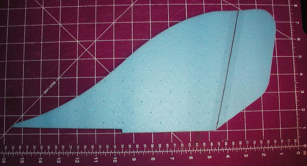
The EPP fuselage has the tail skid incorporated into it for all-terrain handling durability. I actually cut away more of the forward "underbelly" than I should have; once the final taping and landing gear installation were completed, the battery needs to be placed very close to the balance point at the spars. Keeping the EPP foam full depth in this area would be a better idea, so that the battery could optionally be installed within the foam in a battery compartment..
The landing gear was bent from 1/16" music wire, formed to follow the forward end contour of the EPP foam fuselage. Once the wire was shaped, a short cross-brace spreader was placed across the legs at the point where they bend away from the fuselage; it was wrapped in place with kevlar fly tying thread, then coated with CyA glue. The lower spreader was then installaed with the same technique.
The wheels are about 2-1/2" GWS wheels; the keepers are sections of rubber wire insulation stripped off 18 gauge test lead wire, which is a snug friction fit on the 1/16" music wire.
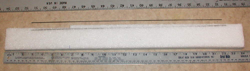
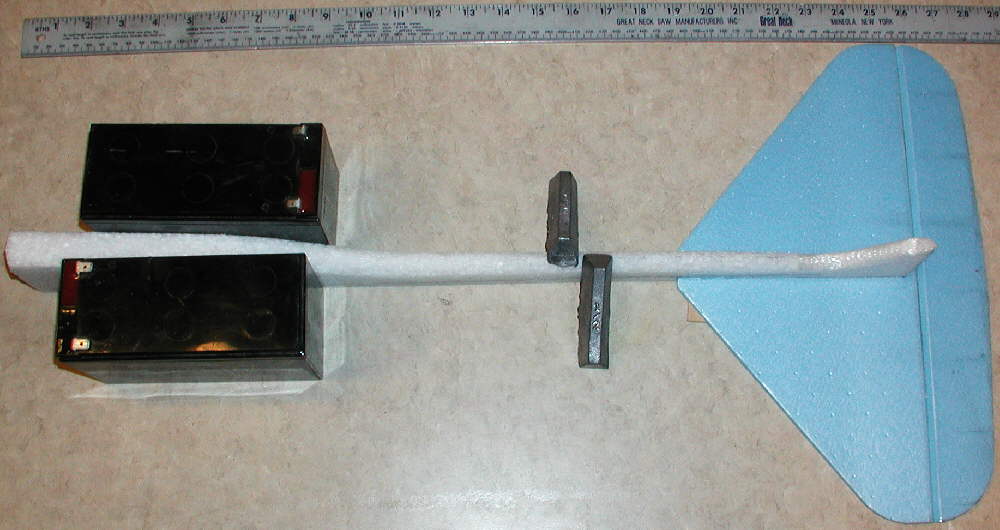
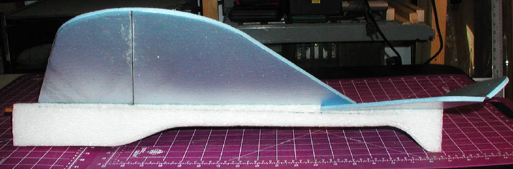
I started making the fuselage by cutting a piece of 1.3 # density EPP foam to size; it's 24" long and 2-3/8" high. It's 3/8" wide at the tail end, tapered to 1" wide at the front end. Next, I cut in the horizontal stabilizer mount deck at a minus 2 degree angle, as shown in the photo above. (That places the flat plate wing at 2 degrees positive incidence relative to the horizontal stabilizer.)
Because ~1/2" thich EPP foam is quite flexible, I used some short sections of 1mm diameter solid carbon fiber rod set into slits on both sides fo the rear section of the fuselage to stiffen it. I made sure the rods were in the slits and the foam was laying straight before gluing those rods in place with CyA glue. (I also added a third short section of C.F. rod in another shallow slit on the underside if the wing / H.Stabilizer joining area to further strengthern the fuselage in this area.)
(EPP can be glued with normal CyA glue- no need to use the foam safe variety on it Hhowever, for gluing the C.F. spars to the Bluecor wing, the foam safe CyA glue must be used, as regular CyA glue eats away the Bluecor foam.)

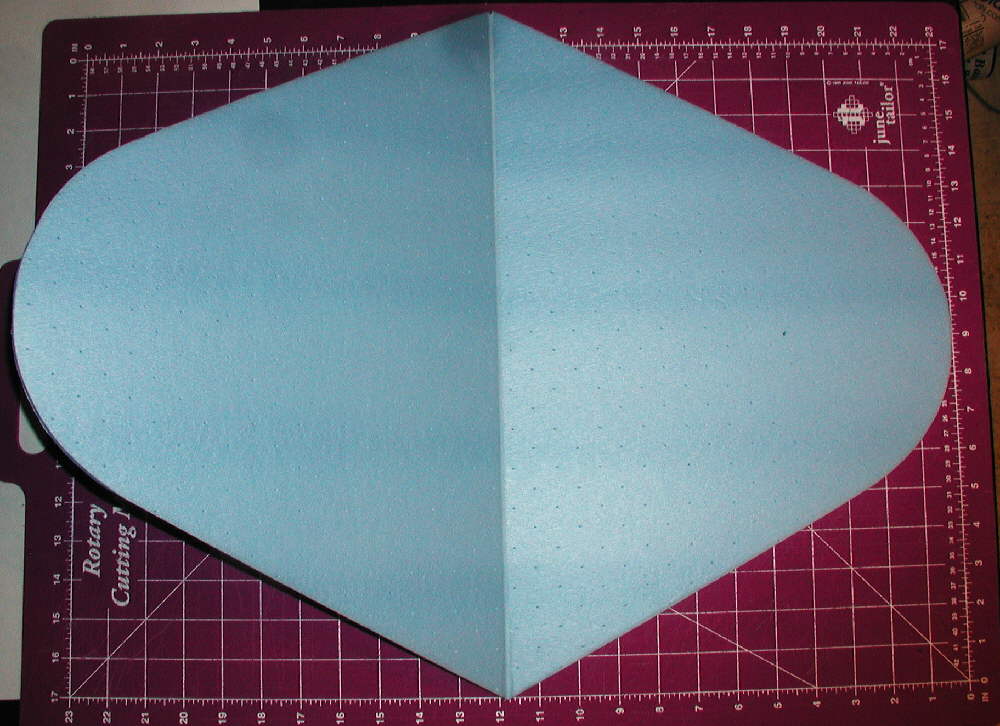
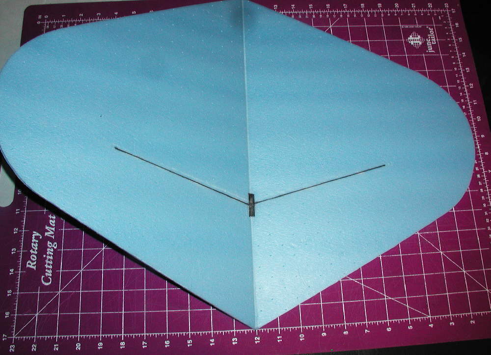
Even though the span is only 23-1/2, I went with high dihedral for fast rudder response, & it paid off well.
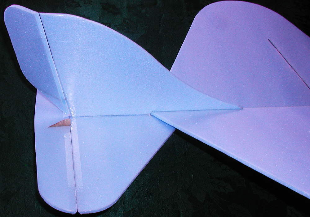
Once the wing is cut out, a slit is made about half way through the foam on the underside. I then made a smooth crease on the top side above this slit before it was folded over a sharp edge. Next, with the bottom side up & the slit / gap exposed, I blocked the center with a 2-3/4" high piece of Bluecor to set the dihedral angle, and ran a bead of hot melt glue in the slit / split to set the dihedral at that amount.

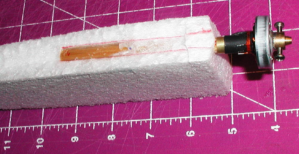
For a motor mount to match the 5/16" I.D. brass tube on my GBv kit motor, I used a 4" section of cedar arrow shaft. I marked it for installation into the EPP foam with both down thrust and right thrust, cut the slot in the foam, and glued it oin place with low temperature hot melt glue.
[NOTE]: I'm suspecting that I built in more down thrust than needed... how much is too much on a flat plate? I'm at roughly 3-1/2 degrees, and I'm now thinking, (after flying CURVACIOUS all afternoon & doing over 50 takeoffs & landings from the narrow snowpacked road in front of my house) that 1-1/2 to 2 degrees of downthrust might be better for high speed flying- and maybe for all around handling.
I also built in about 1-1/2 degrees of right thrust when gluing the motor mount stick into the EPP foam; that seems to be working OK.
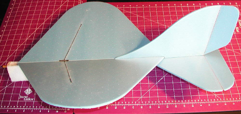
Next, I cut away a shallow vee into the top of the fuselage wing mount area, removing EPP so the wing would have a matching seating area; when the 'saddle' matched the wing's dihedral angle, I set the wing aside.
Next, I glued the horizontal stabilizer to the EPP foam fuselage with 5 minute epoxy glue, blocking and supporting everything in proper alignment while the glue set.
The lightweight 1mm C.F. Carbon Fiber rods do a great job as a spar structure; a 1 meter long piece isn't much over a buck (available from BPHobbies.com), and provided the material for both top & bottom. The Bluecor quickly becomes a type of "stressed skin structure" when neither the top or bottom surfaces at these spars can either stretch or compress.
The installation technique is ultimately simple; make a shallow depression, then 'woodpecker' in a row of closely set pinholes through the surface film into the core foam so that the foam safe CyA can penetrate through the film into the core. Then just glue the 1mm rods in place! (I use a miserly bit of baking soda to kick off / set the foam safe thin CyA, since I can not tolerate breathing the aeromatic amines used in all commercial CyA accellerator products.)
I used a modest amount of carbon fiber tow over the spar joints top & bottom to finish the stiffening, with a bit of baking soda for filler as needed; the result is impressively stiff!
Here's a second, somewhat more detailed description of the process written in response to a question I received:
There are 1mm solid C.F. rods directly above / below each other; I make a shallow depression into the bluecor's film without damaging the film, then take a T-pin and 'woodpecker' a line of holes down the center of that depression so that when the spar is laid in place and foam-safe CyA glue is applied, the glue penetrates into the core foam; the spar is not just glued to the surface.
The carbon fiber rods on the underside were overlapped ~1/8" past each other at the center, and then overlaid with flat carbon fiber tow, and glued with foam-safe CyA, (with a modest amount of baking soda for filler / kicker as needed.)
I then added the top surface ones directly over those on the underside in similar 'woodpeckered' depressions, with the inboard ends poked through the bluecor foam to the oposite surfaces. Again, Carbon fiber tow was overlaid at the area where they touch each other at center, and the CyA glue & baking soda applied.
A type of "truss" (or 'stressed skin structure'?) is made in this way, and the glue penetrating the foam core from both surfaces forms a strengthened 'web' between the two cap strip rods of the truss. Since noe of the four C.F. rods can either stretch or compress, and the strength of the 'web' is very adequate for the stress loads on the web material in an 8 ounce airframe, the result is a lot of stiffness with minimal weight... and at a modest cost of $.99 for a 1 meter length of the rod when bought from
BPHobbies:
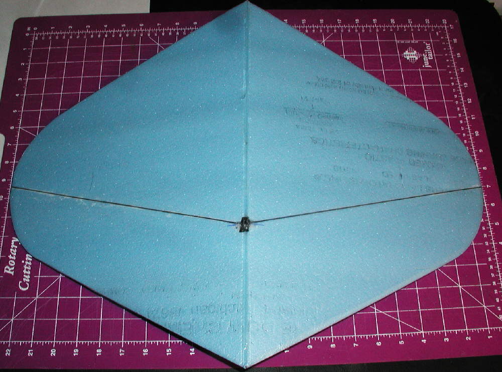
The wing was mounted to the fuselage next, gluing it in place with 5 minute epoxy. (I also did some 'woodpeckering' with a pin on the underside of the wing in the glue joint area so the epoxy would penetrate into the Bluecor 's foam core.) Watch the alignment while the glue sets!
Once the wing mounting epoxy was set, it was possible to cut and carefully sand the lower edge of the horizontal stabilizer so it matched the wing and tail in the mounting area. After another round of 'woodpeckering' in nthe gluing area, the vertical stabilizer was epoxied in place.

Above: Rudder horn glued in it's slot.
Control horns were made from 1/32" birch plywood; long control horns distributre the stresses throughout a much larger area of the Bluecor foam, and are therefore far less prone to being pulled loose later in rough landings, etc. I glue these in thewir sits with foam safe CyA glue.
[ABOVE}: Elevator horn glued in place in it's slot, where it is clear of the rudder's movement.
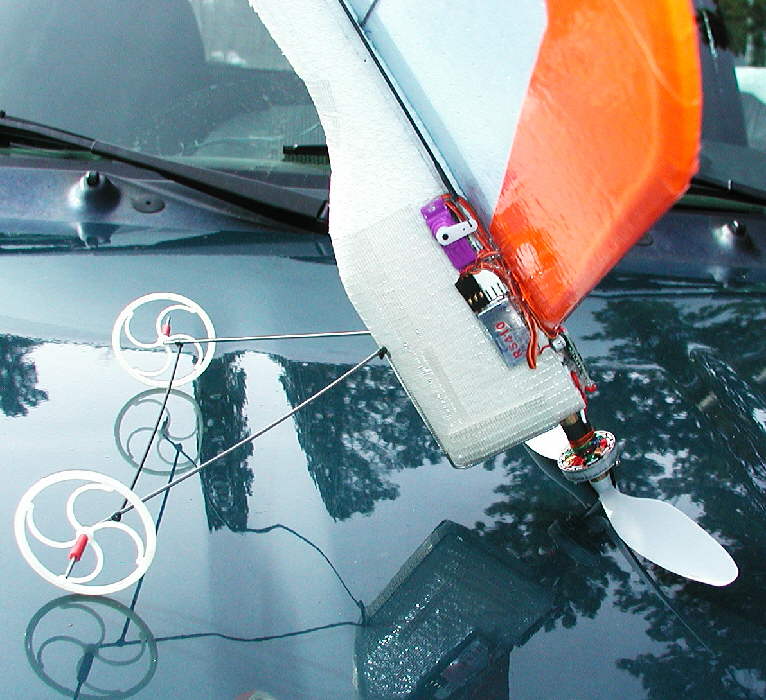
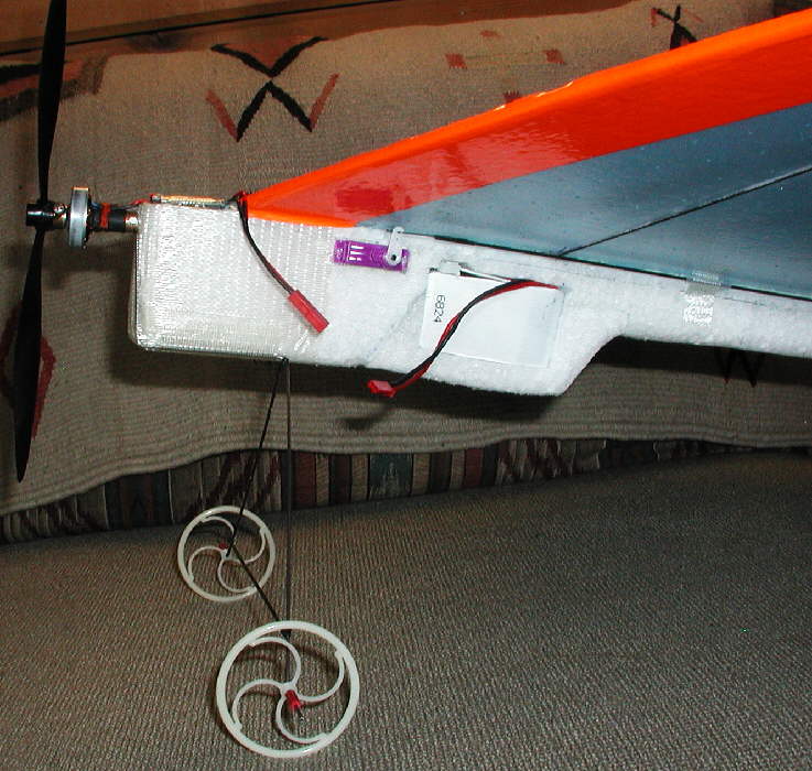
Servos were mounted bottom to bottom in one cutout in the EPP foam, them mounted in place with low temperature hot melt glue under each servo's mounting tabs. Control rods are 1.5mm C.F. rods with two shorter guide tubes on each side of the fuselage; 1/32" music wire Z-bend ends are mounted to the C.F. rod ends with heat shrink tubing. The guide tubes are taped in place with Scotch "Extreme" nylon filament tape (which has VERY agressive adhesive and extreme strength.) Once the radio system is turned on and the control surfaces are set at center trim, the heat shrink / C.F. Rod / music wire joint is locked in place with a bit of regular thin CyA glue.
The receiver is mounted on the righgt side just in front of the elevator servo; the ESC is mounted on top of the front end of the fuselage just behind the motor.
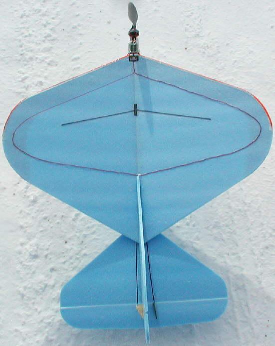
The radio antenna is run in a patern on the top of the wing; it's a red wire on the CORONA RS410 receiver. When I ran out of wire, I completed the full oval patern with a fine tip red sharpie pen!
Nylon filament tape (Scotch Extreme) was applied in a 9/16" wide strip along the wing's leading edge before the fluorescent orange trim tape was applied primarily to the wing's underside; the leading edge is also wrapped with the fluorescent orange tape for good visibility on landing approaches. (More decorative trim may be added to the top surface when inspiration strikes and time allows!)
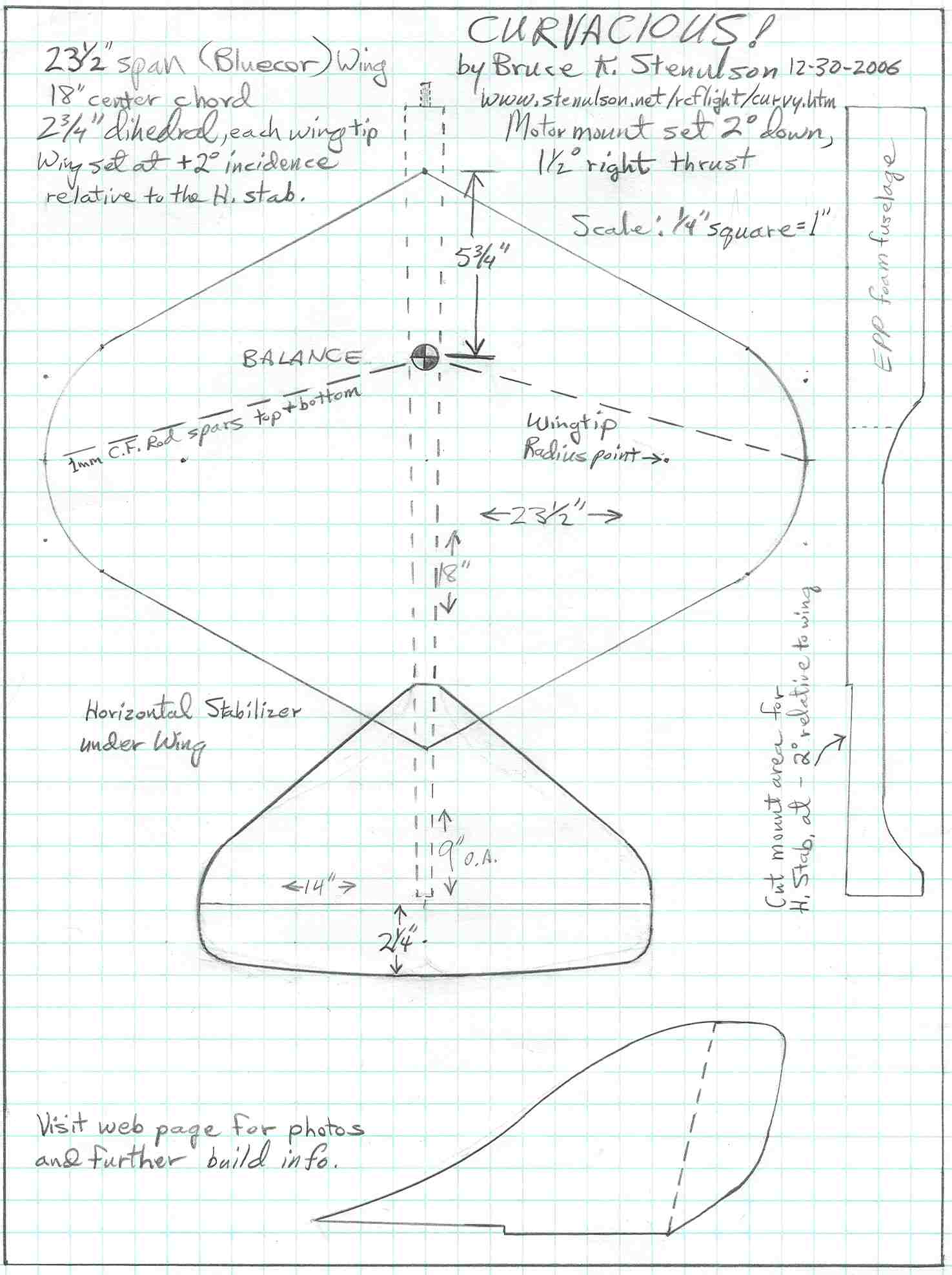
Below is the plan for the CURVACIOUS! It's hand drawn & scanned- not terribly polished, but it has the essential information & dimensions.. Along with all of the photos on this page, you should be able to build one of these for yourself. to save it to your computer, right click on the plan, and select "SAVE IMAGE AS", then specify where you want this file saved. You can then open it separately and print it out.
For those who do not have EPP foam for the fuselage, but do have Bluecor or 6MM Depron, or another building material of choice, you could build up a fuselage from one of those materials, possibly laminating more than one layer together. I buy EPP in 2-3/8" thick sheets from www.flyingfoam.com or www.RCSkyFlyer.com, and cut it on my band saw.

Friends,
CURVACIOUS! went through a modest modification earlier today. I added more EPP foam to the underside (- replacing some I'd cut away in the original build) in order to be able to add a battery compartment within the foam. This will do several things for CURVACIOUS!:
1: Minimize drag by getting not only the battery, but the connectors & extra wire inside the clear plastic covers;
2: Protect the battery from whatever- in's nicely padded in it's resilient EPP foam compartment
3: Keep the battery from being adversely chilled by our cold winter flying conditions, and avoid the loss in performance that comes from chilled batteries.
Once warm weather returns, the clear plastic covers can be replaced with plastic mesh covers for battery cooling; this time of year, that's the opposite of what I need to do!
CURVACIOUS! is ready to fly, carrying a CSRC 2S 800 mAH pack, at 8 ounces.