[Above:] The "DANCER" is now the name for this complete aircraft design. The new design fuselage, designed to fly the 2nd DANCER wing prototype, uses Yellow 'AquaRider' foam for the forward body, a 28" long AVIA .157" diameter tubular C.F. tail boom, 6mm thick charcoal grey Depron for the horizontal stabilizer and elevator, and 3mm thick Depron for the vertical stabilizer and rudder.

[Above:] The heat forming techniques work very well on the Depron tailgroup members to round and firm and streamline the leading edges, while the trailing edges of the elevator and rudder were substantially thinned to about 1/16" or less. (Depron and Bluecor are heat-shaped at about the same temperature - somewhere around 340 to 350 degrees F.)

[Above:] The AquaRider foam material used for this fuselage also heat forms very well (although at a much lower temperature that when heat-forming either Depron or Bluecor.) Both the nose area and the trailing edge of the fuselage body are heat formed and streamlined.

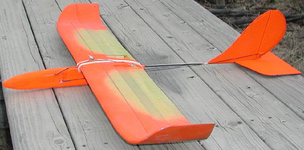
[Above:] The step on this wing's upper layer is now also at 50% of chord, and has been built out to a 90 degree square rear edge. The Yeellow and black paint I used is KRYLON H2O; the Fluorescent orange paint used on the wing tip areas for enhanced visibility is "Odds N Ends" spray enamel; it works fine on Bluecor.
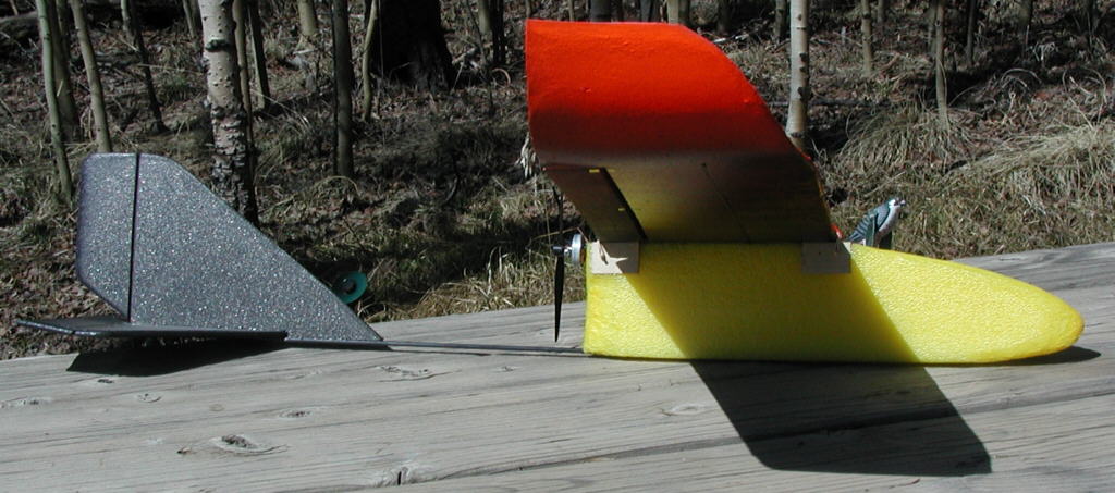
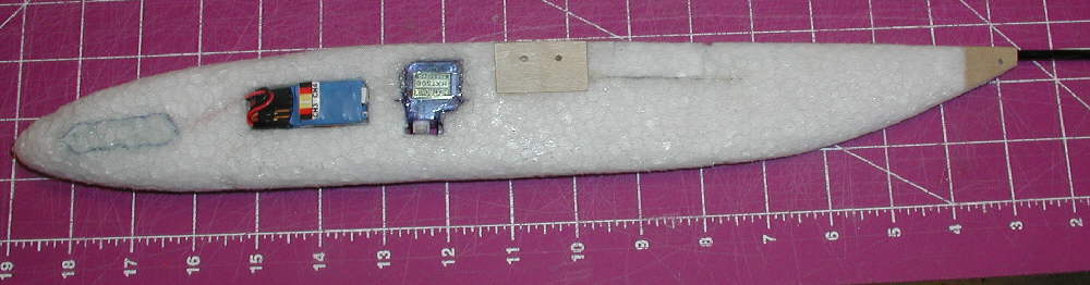
[Above:]The photo avove shows how the vertical and horizontal stabilizers are mounted; the V. Stab. is shorter and elongated in comparison to the "Slim Beagle" fuselage design. The Horizontal stabilizer is also 1" narrower, and elongated, for improved aerodynamics. Rudder and elevator widths are reduced to 2" on the "DANCER". The motor is another 10 wind Y GBv CDROM motor; this wind flys these aircraft well using a GWS 6x3 DD propeller. The fuselage height is just high enough to have an extra 1/8" clearance between the tailboom and the propeller tips. The overall length of the aquarider foam is just under 6", to allow balancing with a 2S 800mAH battery pack well forward in the nose

[Above:] The underside is colored for good visability against either blue sky or clouds.

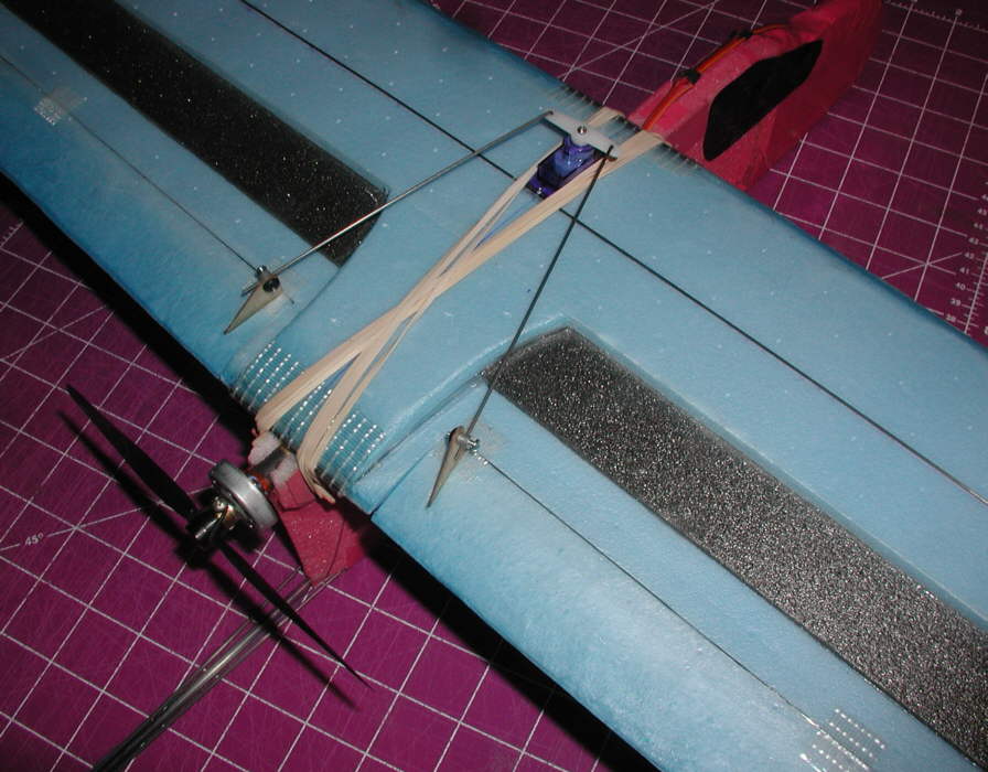
[Above:]Wing mounting is done with rubber bands. The wing mounting bamboo pegs are inserted through 1/32" birch ply side plates; (the 3/32" holes are not drilled yet in this photo). There are also top 'spreader' plates between the side plates, to keep the foam from deforming or compressing in these areas. Two 1mm diameter CF rods were also epoxied in place ater being sharpened and then inserted through the foam, running up from the tailboom to the outrer edges of the rear wing mount plates. This pair of lightweight rods 'triangulates' the wing mount attachment to the tail boom for a more rigid wing positioning in relation to the tailgroup.

[Above:]You can see in this photo that the tailboom extends all the way forwward into the battery bay area, to minimize unwanted flex in the foam fuselage.

[Above:] These are the Depron Tailgroup menbers, hinged and heat-shaped, ready to be epoxied to the tailboom.

[Above:] DANCER ready to fly! View to the west from the KING slope flying site in South Park, Mosquito Range, Central Colorado Rockies
The Krylon H2O paint does add weight, but it bonds well to the BlueCor without attacking the core foam, so I have been using it. I've never come across the 'floral spray'... where do you buy it? It sounds very interesting, so I'd like to try it.
Another note of interest: the 3mm and 6mm grey Depron which I used for the tailgroup on the DANCER responds **very nicely** to the heat forming techniques, using the covering iron! Temperature setting is very clse to that used for the Bluecor- about 340 to 350 degrees F. It's possible to have nicely rounded leading edges and well-thinned trailing edges in a modest amount of time.
The Aquarider foam melts at well below this temperature, so a setting of ~280 F might be closer to what's appropriate when heat-shaping that material. (EPP does not work with the heat-forming / compressing / tempering techniques; it just melts and likes to stick to the teflon surface of the iron.... so it's a process of carving and sanding to streamline the EPP. It does have other structural qualities that I like better than the AquaRider foam, however, so each has it's place.

[Above:] Another view of DANCER at the King slope flying site, looking to the Northwest at another section of the Mosquito Range, with Boreas Pass in the center of the skyline in the distance.

[Above:] Ready to fly weight is about 9-7/8 ounces after taping & trim, balancing at ~38% of chord; flying very smoothly! Wing loading is just under 4.5 ounces per square feet.

I drove up to the top of the KING slope flying site with DANCER to do some test flying in the slope winds. The winds were fairly strong, running from ~15 MPH to over 20 MPH on the wind meter... but from a poor direction.... King faces almost due west, but this day's winds were out of the NNW, towards the rather narrow end of the ridge, which also has a much lower slope angle, and resulting weaker lift.
So after shooting some photos, I launched DANCER for it's maiden flight anyway!
It handled the marginal conditions very smoothly and predictably! Climb is smooth and strong, inverted flight is good, and roll performance is what you'd likely look for in a lightweight hotliner. Response to rudder & elevator are positive and smooth.
The balance is presently at 38% of chord; I'll play with shifting it back toweards 40% when I get a chance to fly thermals in lighter air, and try to define the exact 'sweet spot' for the balance on this wing. Right now, it's very smooth with no hints of pitch sensitivity, even though the wing's leading edge now has a slightly tighter radius than the SLIM BEAGLE's wing.
For having only a 4-1/2 ounce wing loading, this light DANCER is performing very nicely on the slope in far less than 'ideal' slope wind conditions.
So the new DANCER fuselage / tailgroup design is handling very nicely!! A battery compartment and hatch cover were built on the left side of the nose. The nose area around the battery bay is reinforced with 3M Extreme cross-filament tape before the clear plastic hatch cover plate was taped in place. The black 'windows' and logos on the vertical stabilizer were added to dress it up a bit... (then it was time to fly!)
Notes of interest: I'm presently using from 1/16" to 3/32" of 'droop' at the trailing edge on the 7" chord wing. (I've installed Dubro mini EZ connectors on the aileron horns so I can play with and easily adjust this setting.)
~~~~~~~~~~~~~~~~~~~~~~~~~~~~~~~~~~~~~~~~~ Here's an excellent article on: A Physical Description of Flight � by David Anderson, Fermi National Accelerator Laboratory, Ret. & Scott Eberhardt, Dept. of Aeronautics and Astronautics University of Washington, Seattle WA : http://home.comcast.net/%7Eclipper-108/lift.htm
~~~~~~~~~~~~~~~~~~~~~~~~~~~~~~~~~~~~~~~~~
From Jeff Reid's writing in the following linked article titled "How Wings Generate Lift", we see a very important point brought to our attention: that 50% of the lift of a wing is generated in the first 25% of the wing chord. This emphasizes that to achieve greater glide efficiency, it's very necessary to pay closer attention to shaping the airfoil in that front 25% of the wing.
If you look at the RG14 airfoil, you may have an idea of some of the wing shape aspects that I'm trying to employ to reduce drag while ending up with good performance and efficiency across a wide speed range. The KF step on top of the wing reduces drag if effectively implemented, and at the same time reduces air separation. The eliptical upswept wing tips move the wingtip vortexes up and away from the wing's upper surface, so that more of the wing surface is actually generating lift.
That's why shaping the leading edge area of the wing is important; but it's also why I wanted to nail down the aspect of the 90 degree top step first, before completing the L.E. shaping on this #2 wing. http://www.physicsforums.com/archiv...hp/t-107565.htm
~~~~~~~~~~~~~~~~~~~~~~~~~~
written 5-01-2007] Originally Posted by Tony65x55
Question by Tony: "Viking, nice bird. Looks like you have a fine flyer. With the wing mods you completed, does it fly as good as the last one? Did the LE mods have the desired effect (if you posted this, sorry, I missed it) Thanks, Tony
[BKS Reasponse]:)I had thinned the leading edge substantially (heat - forming / compressing using the covering iron) before I painted the wing. To be more specific: I shaped & compressed the upper surface foam, contouring it back for ~1-3/4", shaped the leading edge radius at roughly 25% to 30% of the wing's total thickness, and also shaped / rounded up the first 1" of the chord on the underside of the entire leading edge, giving the airfoil more of a 'Phillips Entry' for smoother handling and penetration at high speeds, as well as clean efficient gliding at low speeds. Some of the photos are sharp enough to show the leading edge's contouring, as well as the extensive thinning of the upswept wing tips and the trailing edges.
Competition Glider guys know 'it's all about the airfoil', and the RG14 is a superb thin high speed glider airfoil. (It's also excellent for lightly loaded foamies which you want to have the ability to both penetrate wind, and to glide efficiently in light thermal lift. At a heavier wing loading, the RG15 would be more appropriate; in a more flat bottom airfoil, the E205 has served me well, but it was thicker than I wanted for the DANCER wing's build.)
Print out a copy of the RG14 at 7" chord in the Profili software (free evaluation copy does this OK), then look at it- make templares from it to use if you want- and figure how to sand and carve away and heat compress the excess foam that doesn't fit within the airfoil shape template, and you will have a good start at forming a cleaner, more efficient glider wing from Bluecor, Depron, etc.
I wanted cleaner penetration and more lift while staying with a thin wing. The beauty of DANCER's wing is that it starts with two 6mm layers of FFF / Depron, and a 1/16" thick spacer to get to ~7.5% thickness - basic and fairly easy for the novice builder to put together without warps or twists!
Jeff Reid, in the writings on the PhysicsForum discussion I linked for everyone, pointed out something that should be carefully contemplated:
"50% of the lift of a wing is produced by the front 25% of the chord of a wing."
That emphasizes how significant the shaping of this section of a wing can be when we're looking for efficient glide, as well as wind penetration. If you don't shape it, then that front 25% of the wing chord is probably not doing as much as it could, and the glide on a glider wing will not be as efficient as it could be.
For 3D aerobatic powered park flyers and planes that are intended for hovering and high-alpha maneuvers, symmetrical and flat plate wings perform fine... but for really EFFICIENT gliding as well as smooth wind penetration at higher speeds, the shaping of the front 30% of the wing can contribute dramaticly.
The 90 degree K-F step, when built at 40% to 50% of chord, helps keep air from seperating from the surface of the aft 50% of the wing's chord in the areas where a step is implemented. This is why it helps KEEP the rear part of the wing from loosing it's ability to generate lift at slower speeds and at somewhat higher angles of attack. But it doesn't affect the air flows / pressure differentials forward of the step very far, in the front 30% to 40% of the wing's chord....
That's what the front 30% section of a wing's airfoil shape, and the resulting 'camber line' of the airfoil, can do when shaped. Figuring out how to accomplish it in a fairly simple build using FFF / Depron material is what the DANCER's design evolution is all about.
~~~~~~~~~~~~~~~~~~~~~~~~~~~~~~~~
You asked about comparing the first constant chord wing, and the DANCER's tapered chord wing; I need another couple thermal flying sessions before I'll offer that evaluation.
First I need to fine-tune the balance on Dancer; it's a bit forward of ideal for most efficient thermal gliding capability. I'm looking for neutral elevator trim, and both blalnce and declage are involved in achieving that. I'm looking to get towards a bit LESS pitch stability than I have now for more efficient glide... it's a trade-off that is exactly a 'balancing act'!
I built in slightly more positive wing incidence on the DANCER's fuselage than on the "Slim Beagle" fuselage, so I want to compare those, and test by shimming the T.E. of the DANCER's wing to remove a bit at a time; a minimal wing incidence angle of +1-1/4 to +1-1/2 degrees relative to the horizontal stabilizer should be ideal for DANCER's RG14KFv airfoil, and it's intended wide flight performance envelope: light hotliner to thermal floater.
I may try to get in some thermal flying today... it's a brilliant Colorado Blue Sky morning, & good thermals should be forming by 10 AM... have to take some time away from work to take advantage these ideal flying conditions!!
More soon! Whatever you do, howerer you do it, HAVE FUN doing it!!
[Question]: "Viking, are you skinning your FFF before the heat shaping?"
[BKS Response]: For the extensive shaping I'm doing on the wing leading edges, peeling the Bluecor might help; the surface film can be also heat formed without removing the film, but if you are melting a lot of it, it does build up a higher density. It can be compresed & smoothed, but removing it selectively would be worth doing in certain applications..
For rudder & elevator trailing edges, I would not remove the film; I'm loking for firmer high-density edges there.
DEPRON is forming very nicely; carving / sanding to a rough oversize form, them finishing with the covering iron to a smooth finish shape might be the ultimate approach, rather than heat-compressing a lot of volume of foam.
[5-01-2007]: Friends,
Dick Kline asked me yesterday if I had any video of DANCER flying. I regretfully told him that I mostly fly alone, so getting video was a challenge.
But then, later this morning, I got to thinking of the tripod I had sitting in the corner, and so I decided I'd set up my digital camera and give it a try. I had never tried this before, and if you have shot video with a digital camera, you already know that the frame rate is slow when shooting video at 640 pixels wide...
The other issue was trying to have an idea of the modest sized 'window' of sky that the camera captures, and to try to fly most of the time within that window... another first for me!
Wind noise is excessive on the video, as another storm front was rapidly moving in- not thermaling conditions. Most of the flying is more 'hotliner' flying rather than gliding, but you'll get an idea of the performance capabilities, from the hand launch to the hand catch.
This is only the second day that DANCER has been out & flying; final balance tweaking remains to be done on another quieter day. (I didn't complete the work I planned to do this morning until the storm clouds were on the horizon and beginning to march across the Park at an impressive rate!)
So if you have high speed internet access, and you don't have a problem waiting for this 56MB file to download off my server, here's the link- let me know what you think!
NOTE: This may take a while to download from this server!
~~~~~~~~~~~~~~~~~~~
FEEDBACK Comments:
"AWESOME!!! INCREDIBILE!!! MAGNIFICENT!!!"
"Talk about Big Sky... the setting was great. And the DANCER looked very graceful. It's seems to move through the air effortlessly. I am just so impressed with everything.
How does its penetration through the air compare with other airfoils?
Thank you so much for this great big pleasure.
If I can help you in any way, please let me know. You are amazing!!!! "
Dick Kline
[BKS Reply]: Comparison? I'll just say this: in it's size and weight class, it stands alone! Penetration is exceptional for a wing that is so lightly loaded; 4.5 ounces per square foot is VERY light, yet it's handling the slope winds very nicely. The power system is well matched to this wing's capabilities- another piece of the overall performance picture.
I just posted the link to the video on RCGroups, so others can also view it.
Thanks for all of the kind words & ongoing support and encouragment!!
~~~~~~~~~~~~~~~~~~~~~~~~~
[RCGroups member comment]: "Looks very nice Viking!!! The speed looks great; it looked like the Dancer had no trouble at all penetrating the wind. How windy was it?
Great job!!"
[BKS Response]: Thanks!
The winds weren't all that bad - maybe peaking at 15 MPH; on the video you can see how the DANCER was being rocked in my hand before I launched; but it was easy for the DANCER to fly through, a bit turbulent during slow low landing approaches, but not conducive to allowing lower level thermals to shape up decently. The wind noise in the camera's microphone is quite noticable... (this is the first flying video I've set up to shoot.)
[Added 5-5-2007]
Friends,
The 7.5% thick wing with the KF step treatment on top at 50% of chord is flight proven; it flies very well.... but it's sleeker and faster than what many aircraft designs may want- especially for park flyers designed to fly in smaller areas.
The question of how to build a thicker wing, using sheet foam - Bluecor and / or Depron, and fairly simple assembly techniques, has been on many people's minds. The potential problem with thicker wings is that they may have a greater drag penalty when the step depth exceeds ~60% of total airfoil thickness at the step. This in turn could result in reduced flight / glide efficiency.
But the concept of using a second step between the 50% of chord point, and the trailing edge, merits investigating... (and it lends itself well to working with layered sheet foam materials, too!)
Below is a diagram of the new prototype that's on the building table now. It has a total thickness of 9% of chord. The wing's overall dimensions are 48" span x 7" chord [before the wing end areas are upswept], so that direct comparison test flying can be done, comparing against the other two wings built at 7.5% thickness for the DANCER.
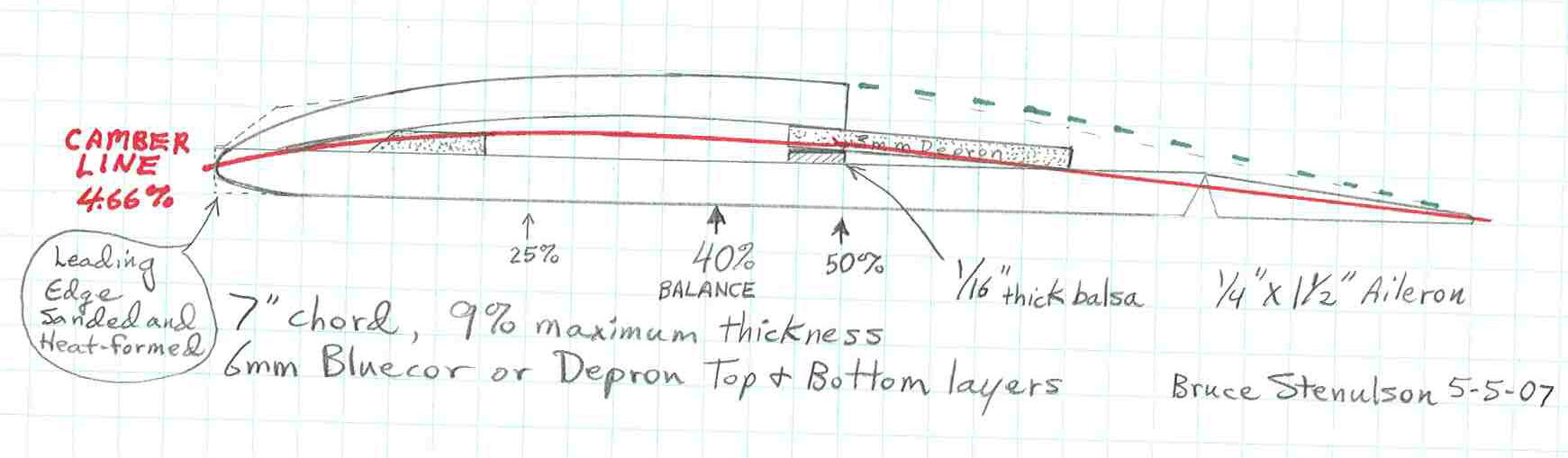
1>The bottom layer is Bluecor (or 6mm Depron).
2> A 1/16" thick x 5/16" wide balsa strip, 39" long, is added with it's rear edge at the 50% of chord line.
3> a 3mm thick sheet of Depron, 1-9/16" wide by 39" long is then overlaid as shown in the drawing, extending over the balsa strip in front, and 1-1/4" behind the 50% of chord line. It also has a 90 degree trailing edge step. This places the secondary step at 68% of chord.
4> Another strip of depron, 5/8" wide x 39" long, is laid in with it's front edge back 7/8" from the lower main sheet's leading edge. This is included to help form the forward curved shape of the airfoil, and the resulting "Camber Line", drawn in red on this diagram.
5> The upper layer is another sheet of 6mm thick Bluecor (or Depron) that is slightly rolled to form the curvature of it's upper surface before being glued to the three contact lines. It has a 90 degree step angle, with it's rear edge at the 50% of chord mark. It is then glued in place along the three contact lines: leading edge, front depron spacer strip, and at the step.
6> The wing tip areas have been rounded back to match the profile on the previous DANCER wings, and will be upswept an equal amount. 1mm CF rod cap spars will also be added on top & bottom; since they also act as "turbulator spars", starting the surface boundry layer air turbulation process, I plan to locate these at 33% of chord, as I did on the first DANCER wing.
7> I'll again use light weight balsa aileron stock, with each aileron being close to 18" long.
I may be able to complete this new prototype wing and have it ready to fly later tomorrow if weather conditions permit.
(It's still snowing lightly as I write this, so I'll have to see how the weather shapes up for a test flight tomorrow afternoon. I'll report the observations when test flying is completed.)
The fun continues!!
[*** OH... the dashed gleen line in the upper rear section of the airfoil? That's my conception of the 'virtual airfoil' boundary between the lower turbulent air that remains turbulated and attached to the wing's rear surface, and the higher speed / 'lifting' airflow above that boundry.... At this point, it's simply how I conceptualize it for now!] ~~~~~~~~~~~~~~~~~~~~~~~~~~~~~~~~
[Originally Posted by tolladay]:
"Beautiful work Viking. The drawing really really helps to visualize, especially for us poor artists types who see better than they read.
I'll note that you did not include the negative reflex of the ailerons in their final position, or will you be testing this as well? (knowing you, you'll be testing 3 other things to boot )
Looking forward to hear about your progress.
re: thinner wing. For a while I've been wanting to design a fairly slick (as in not draggy) glider out of FFF. This was the initial reason why I started asking about your wing as it looks perfect for this application. Maybe even an 8' span wing (two 4' sections joined at the middle) with ailerons on the outboard, and flaps in the middle for full camber manipulation.
Who knows? Maybe the double step wing will perform even better."
~~~~~~~~~~~~~~~~~~~~~
[BKS Response:] Tolladay,
I'm expecting this airfoil / wing to also fly better at higher speeds & in slope winds, and also ride thermals better, with a bit of trailing edge droop set in the elevons- maybe only 1/16" to 3/32" max. at the elevon T.E.; It builds out flat fairly easily. Yes, everything will get tested!
On an 8' span wing, spar structure design would be more of an issue. There's excellent structural strength / rigidity at the 48" span size using just the two 1mm CF rod 'cap spars' bonded to the top & bottom surfaces of the Bluecor , as they can neither stretch nor compress... the result is a structure similar to an I-beam, accomplished with only .08 ounce of material.
The thinner 7.5% thick wing will very likely test out as better for handling higher speeds, and will have better wind penetration capabilities at light wing loadings. This 9% thick wing is being tested for slower flying designs.
The simplicity of build is also being pursued; stacking pieces of sheet foam to end up with a higher performance wing / aircraft is something that any foamie builder can do. (It's a nice alternative to hot wire cutting of foam cores!)
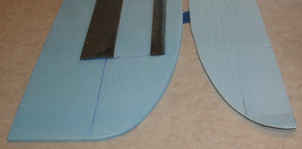
Above: This photo shows the internal strip spacers; the 1/16" thick balsa strip is under the front edge of the rearward wider 3mm thick piece of grey Depron.

Above: Top layer of Bluecor is shaped, has the curvature rolled in, and is ready to be glued in place; I used 12 minute epoxy for this job so I'd have enough time to apply the glue to the three contact areas. The front narrow 3mm Depron strip has also been heat-compressed along the front edge, for better contact & final airfoil shape.
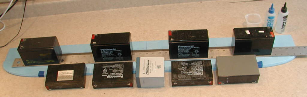
Above: Epoxy has been applied, and the top layer is in place, throughly and evenly weighted down with old Gel Cell batteries while the epoxy sets up.
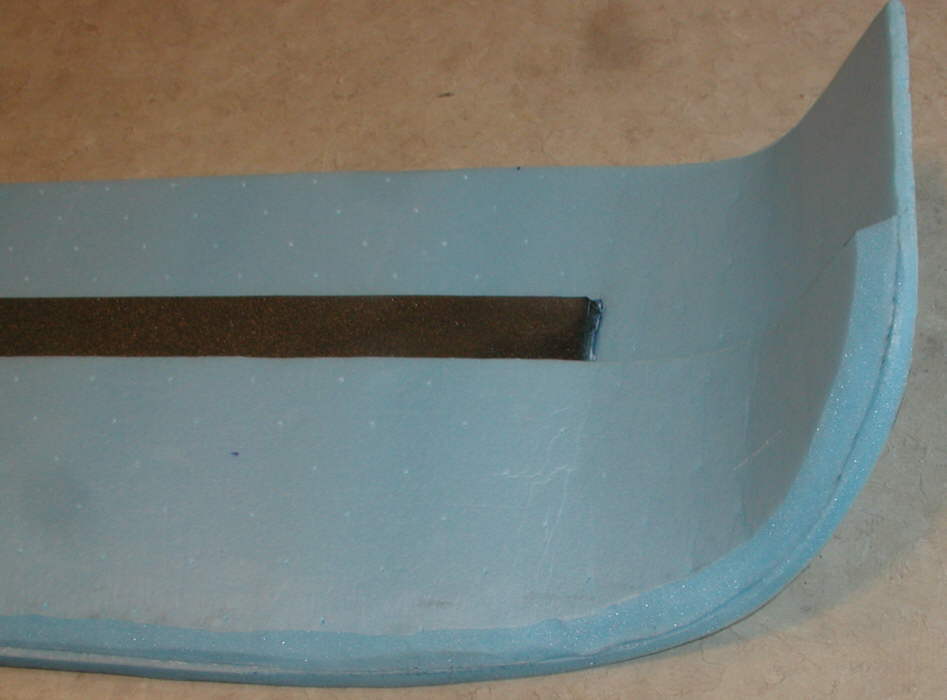
Above: Next, the wing tips were shaped into the upsweep, with the outer edge ending up at 2.5" off the building surface. Hot melt glue was applied between the two Bluecor layers, then a heat gun was quickly used to heat-temper the upswept curvature into place. The excess Bluecor was then carved away close to the final form for the Covering Iron's application to achieve the final heat-formed contours.

Above: This photo shows the final smoother heat-compressed and tempered leading edge.
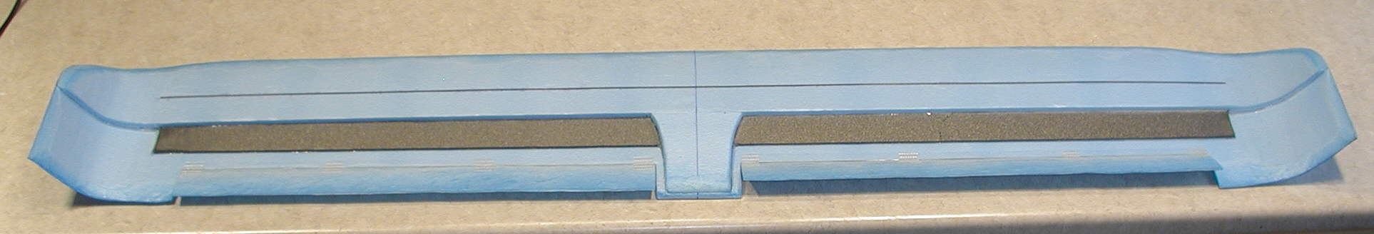
Above: Heat-formed Bluecor ailerons are hinged in place. The top rear center doubler is in placed and shaped, and the 1mm CF rod spar caps have been glued in place at 33% of chord. Balance should be close to 40% of chord for most efficient glide.
Above: CF rods have been hot-melt-glued to the center leading and trailing edges and overlaid with Scotch Extreme tape. Aileron servo and linkages are in place and set, ready to fly!
Weather has been quite snowy late today, so the flight test report will have to wait for a better day!
[Added Monday afternoon, 05-07-2007:]
Friends,
Despite snow fluries still drifting down, after running to town in early afternoon to ship a package, I decided to get in a short initial test flight on the new 9% thick wing. Light was somewhat flat but bright, & the flurries weren't too thick; best of all, the air was close to calm and smooth.
Initial evaluation? This wing is really SMOOTH! I'm going to say at this point that the glide is flatter, and it's able to glide more slowly than the 7.5% thick DANCER wings (with their much thinner leading edges and lower airfoil camber lines) without beginning to 'mush'.
Since the world is covered either in slushy snow or the mud on the dirt road I'd launched from, I was gonig for a hand catch... but on the first five setups, this bird just wasn't coming down... so I'd power up and go around again! I got a perfect grab on the fuselage nose as the next snow squall was moving in thicker, and called it enough for right then.
So even though this aircraft (9% DANCER DS wing on the "Slim Beagle" fuselage) is 1/4 ounce heavier than the 7.5% thick winged DANCER, it appears to be gliding flatter / even more efficiently, glides cleanly at slower speeds, and has less pitch sensitivity than the thinner wings with their sharper leading edges. It seems to fly a bit slower under power, but is smoothly responsive.
Balance is at 41% of chord; flying weight of 10-1/8 ounces on a 2.22 Sq. Ft. wing = a wing loading of 4.56 ounces per square foot.
Is the secondary step further reducing drag to improve the glide? Quite possibly; that was the intention.
How much of the improved slow speed glide performance is due to the thicker wing with it's well shaped forward section and the higher camber line? A significant portion, undoubtedly.
The overall result is a sweet flying wing that handles like it's 'on rails'..... smooth!
More soon!!
Quote: [Originally Posted by Tony65x55 on 07-16-2007] "I'd start at 20% Based on a 16" wing root that would put the CG at 7" from the LE, measured at the root. The KFm usually likes a CG more aft than most. " Tony
[BKS Response:] I'll offer a bit of further insight if I may:
On the DANCER, with the top KFm step at 50% of total chord, the ideal/ most efficient thermal gliding balance is at about 40% of chord. I'd expect a conventional RG14 Airfoil, of similar leading edge shape and layout & at a thickness of 7.5%, to glide well with the balance set at 30% of chord, so the KFm step addition back at 50% of chord seems to effectively move the center of lift back about half of that difference- to 40%.
My SPINNER is an aerobatic 3D type design, and the first two were built with flat plate Bluecor wings. Balance is ideal at 30% of chord. When I built the third SPINNER, I tripled out the leading edge back to the 30% of chord mark, with a well rounded leading edge and a 90 degree step at the back edge of the added layers at 30% of chord (on both top & bottom.) This aircraft still balances & flies very well with the CG at 30% of chord (because the KFm steps were not located farther back on this wing.)
It flies more like a thin symmetrical wing, rather than the previous flat plate wings, largely due to two aspects: first, the well rounded 3/4" thick leading edge on the wing is less pitch-sensitive. Second, with the very rigid wing structure resulting from the triple layer build, there's no 'camming' of the wing compared to what is seen on thin flexible flat plate wings when transitioning from up-loading on the wing to down-loading.
In working with FFF materials, it's really nice to know that there is no drag penalty when building in the 'discontinuity' which we've come to refer to as the KFm step (- at least, no drag penalty if the step is not too deep?)
And in fact, there are indications that the wing can possibly fly a bit faster / more cleanly than a 'fully shaped conventional airfoil' *IF* the KFm steps are implemented properly..... an observation which still confounds the classic old-school aerodynamicists... (which relates to why golf balls fly farther with their many little dimples than they can be driven without those little dimples / 'discontinuities' on their surface!
This Wednesday the writer from Popular Science is coming up to interview me about the KFm revolution in Foamy RC design, and to see the DANCER do it's thing... it should be an interesting day!
The Fun Continues!!
VIKING
[Discussion posted on 07-18-2007: ] Quote: Originally Posted by davereap
..." It does make me wonder how critical it all is, is there a minimum usefull step depth, or a maximum.
From trials the chord %ages that improve the glide have been found, but with some planes they are including the ailerons and on some they dont. Some use top steps some use bottom steps. Some planes are fast some slow. There are so many variables that it is difficult to specify what will work best for a particular plane.
What is not in dispute is the improvement you can get with the step.
It is good for us all that lots of variations are being tried, the more results we get, and even poor results count, the better our understanding will be of the whole thing."
[BKS Response:] Dave & friends,
Sailplanes sometimes use either "turbulator spars" or the addition of "trip strips" on the forward section of the airfoil's upper surface to effectively turbulate the boundry layer air, thereby reducing air separation... so the minimum height / thickness of a 'discontinuity' / step to achieve this effect can be quite minimal. The nice thing we now know that's relavent to building Foamies from layered sheet FFF / Depron, etc., is that there is not an observable 'drag penalty' from building the step in most cases, at the speeds at which these foamies fly.
I believe we can experimentally demonstrate that when a optimally located step (-let's say, top step at 50% of chord) exceeds a certain height / thickness, that it may generate more drag than a lower step height would generate on the same wing. This is perhaps why such wings at 7.5% to 8% thickness are understood to generate lift and still glide fairly efficiently, but thicker wings with deeper top steps do not perform as well / glide as efficiently.
My third DANCER wing was built at 9% thickness as a test, but was built with a staged double step, to keep the depth of the steps shallower. (I wanted an airfoil with a higher camber line for slower flight tasks, which would still fly & glide with minimum drag and therefore glide very efficiently.)
Flight tests are still ongoing. In the early half of May, I flew on days where this thicker wing seemed to be able to glide in soft lift & dead air at lower speeds & with less sink than the 7.5% thick, single step wing could in the same air. (This was in the 16% lower air density of my 'home' flying area here in the central Colorado Rockies at about 10,000 feet elevation.)
In comparison, I flew both of these wings in Wisconsin during the latter half of May. Skies were hazy / lightly overcast & I was not flying in a area that was generating thermals, so I was flying in thicker 'dead' air. In those conditions, the 7.5% thick DANCER wing outperformed the 9% thick wing. It simply felt more 'lively' and responsive. (Elevation there is roughly 600 feet ASL )
TOLLADAY's experiment of adding the step to the underside of his undercambered wing on his Cub was very revealing; he found that it produced a heavy drag penalty, besides increasing flying weight / wing loading, without any perceived desirable affects.... (- hopefully I've summarized his brief report adequately!) So from this we see a dramatic demonstration of how adding a step can possibly degrade the performance of certain designs.
When in doubt, build it several ways & test fly it... that's the only way to really prove what offers the optimum performance.
The glide efficiency performance testing is where I've focused some of my design & prototyping work, since the results are most obvious in the degree of power-off glide efficiency achieved by variations.
For other designs / performance tasks, increased drag may not be an issue of concern. Whatever anyone chooses to build & fly, have FUN doing it!!
VIKING [Bruce Stenulson posting as VIKING60 on RCGroups]

[Above]: Here is the new wing, mounted temporarily on a HLG Pod and Boom fuselage. The ailerons are hinged with Scotch "Extreme" cross-filament tape in threee places on each aileron's top surface. A 1/2" wide section of the same tape is used on the underside of each of those tape hinges, too.
This HLG fuselage's EPP nose section will be further shortened and shaped to a slim streamline profile once all servos are set, and the balance / placement of the receiver battery is determined.

[Above]: This is another view of the upper surface of the wing, showing the aileron control horns and hinging tape placement.

[Above]: A view of the underside of the wing, and the temporary EPP foam fuselage's shape. A .157" diameter AVIA pulltruded CF tube is used for the tail boom; the bluecor tail members have their edges thinned and firmed by the heat-forming technique.