


Wingspan : 100"
Wing Chord : 12.1" center, tapered at wing tips
Wing Area : 6.57 square feet
Airfoil: SD7037
Fuselage Overall Length : 48.5"
Controls: Camber changing flaps; Ailerons; Rudder; Elevator; Throttle; CROW / Butterfly available for landing control
Flying Weight , E-Powered: 71.5 Ounces with 10 cell SANYO 1250 SCR battery pack installed.
NOTE: Just for reference- another Spirit 100, built from the kit as a glider, has so much lead required to balance the aircraft that it weighs 67.75 ounces WITHOUT a power system!)
Wing Loading : 10.88 ounces per square foot
Motor : 20 sized Cobalt (Brushed) motor, 8 wind : CERMARK CEM2008
Propellers : Freudenthaller Aeronaut blades 12x8 tested on 10 cells here at 10,000 feet; 40 amps on non-peaked pack.
Battery: minimum configuration = 10 cell 1250 mAH SCR SANYO NiCad @ 15.5 Oz.)
Speed Control : Custom Built SC-6 ESC design; this one built with two IRF2804 MOSFETS, for ~.0012 Ohms ON resistance; thin sheet copper heat sink on BEC voltage regulator ; sheet aluminum heat sink mounted on MOSFETS
Radio System used: FUTABA 9Z Transmitter; GWS 8 Chanel Dual Conversion Receiver; 5 Hitec HS-81 servos for rudder, flaps, and ailerons; one TS35 BB servo used for the elevator
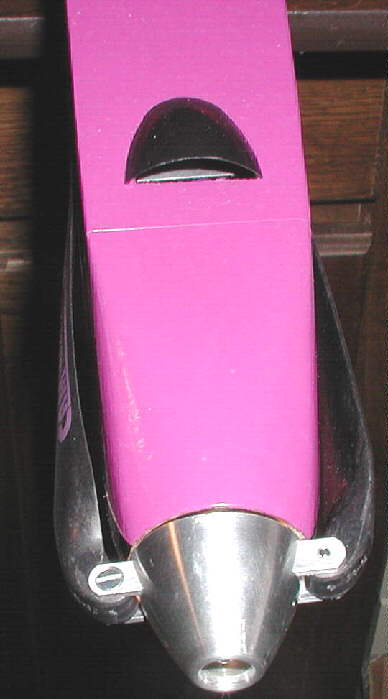
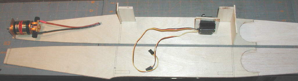
The photo above gives a look at the clean nose, acheived by using a rolled 1/64" plywood tube to mount the motor. The cooling air intake scoop on the top access hatch directs air over the SC6 speed control's transistors, which are mounted on a heat sink just under the air scoop, and then on past the battery. The vented spinner runs more air through the motor & past the battery pack for cooling. The tail end of the fuselage has an opening to allow for cooling air flow exit.
I mounted two of the lowest resistance TO-220AB size MOSFETS presently available (IRF2804) to the sc6 ESC board, with a sheet aluminum heat sink attached to them and then anchored to the fuselage left side wall just behind the motor. With adequate heat sinking, this motor / ESC combination can likely be propped to run on ten cells at 50 amps or more without overloading the ESC. The motor brushes are large and well-vented; other similar motors in my Viento and VIKING 60 are holding up well.
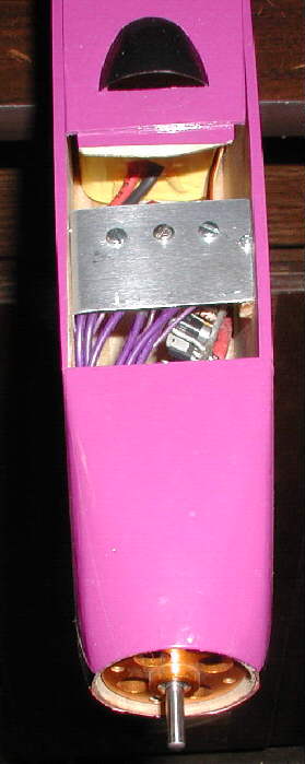
The photo above shows the heat sink installed well forward under the hatch, with the hatch itself slid forward close to it. You can just see the front edge of the ten cell SANYO 1250SCR battery pack in the area behind. There's lots of room for up to a 14 cell pack, if desired; my concept, however, was to run a larger folding prop on ten cells on this 8 wind motor. I'm intending to prop it for about 100 watts per pound, or somewhere between 400 watts and 450 watts, to start. Initial tests show a static draw of 40 Amps running a set of 12x8 Freudenthaler Aeronaut folding blades on the 36mm vented spinner, which are available from Hobby Lobby.

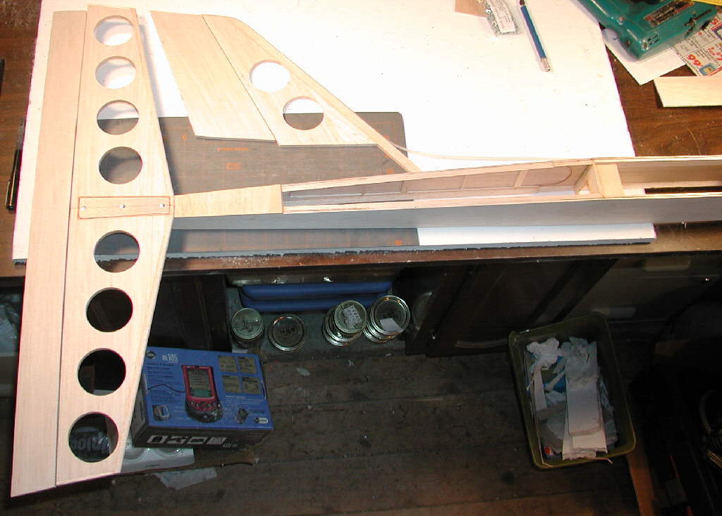
I started the fuselage plan modification by determining the motor mount position. I built it to give enough clearance for this particular motor, with it's extended brush holders. A rolled 1/64" plywood tube was later used instead of the fiberglass bulkhead shown in the photo above, to allow the narrowest folding prop midpart / spinner to be used on this design.
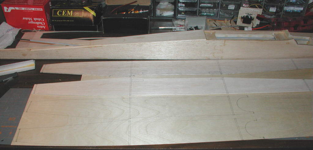
Fuselage outer balsa panels get a 1/32" birch ply doubler panel on the inner surface, running from the front end to just behind the trailing edge of the wings. (The standard kit built glider fuselage is seen in the background of the photo above.) The front end of the fuselage is designed to allow about 4 degrees of downthrust in the motor installation, as referenced to the horizontal stabilizer.
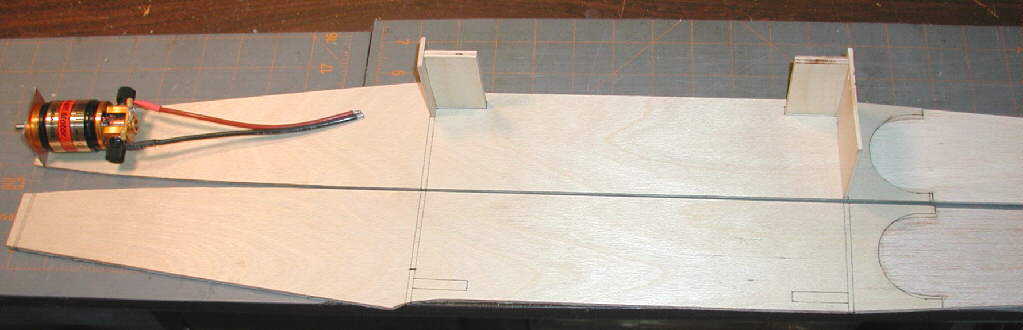
The wing bolt-down plates are positioned to match the wing. The interior of the fuselage, however, needs to be laid out in an open configuration to allow ease of battery positioning to achieve final balance. Fuselage width was set at a minimum that would handle the size of the battery packs I anticipated using; I have 2-1/8" inside between the side panels.
A servo tray was designed to fit to the rear of the area under the wing; it was finally glued in place when the final balance was verified after construction and covering was complete. Balsa triangle stock was used in many places to add extra strength as needed. The forward fuselage belly is made from 1/16" birch plywood, for better battery carying & landing durability.
Here's the rear end of the fuselage, with the removable horizontal stabilizer and vertical stabilizer. You can also see the rear side panel reinforcing strips that run vertically, as well as the triangular balsa longerons. I actually kept the tail end of the fuselage about 1" wide, and about 1" deep, to provide a cooling air exit for the motor, ESC, and batery's cooling air flow
I used Sullivan Carbon Fiber control rods in this project in the rear of the fuselage.
I hope these photos inspire a few of you to do a similar project! (There are really no plans as such- I did some overlay drawing on the original Spirit 100 plan, and started building from there.