
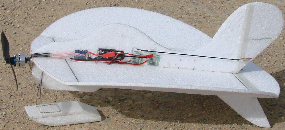
The photo below shows the FLIRT set up with dual front wheel landing gear, with a 10 gram motor installed up front.
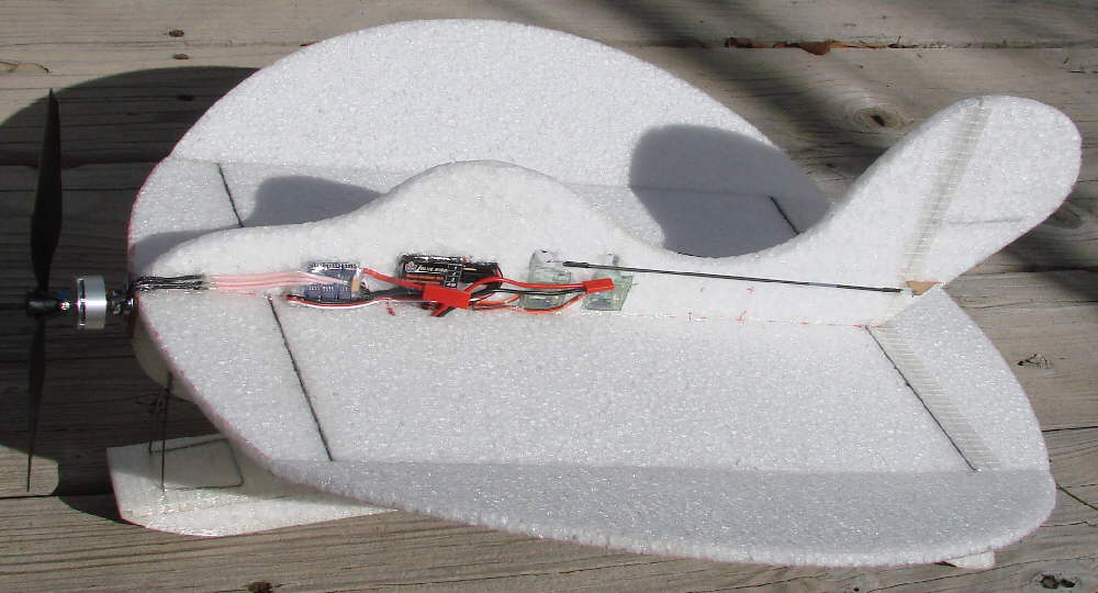
The photo below shows the FLIRT as it was first completed, with the EPP foam mono-ski mounted.
The FLIRT was designed with a full length upper fuselage where the ESC, radio receiver, and servos are all easily installed. The slightly thicker EPP lower fuselage is designed to allow room for carrying the battery within the foam, directly on the center line, and out of the cold winter air. The lower fuselage also provides adequate support for the extremely light weight mono-ski mounting, or for the later dual wheel landing gear setup. It's also best to carry the battery below the wing mounted with velcro on the right side, or possibly carried within a compartment in the EPP foam.
It's amazing how aerobaticly this Rudder / Elevator aircraft can fly. The 24 degree dihedral angle under each wing tip panel allows for this type of agile handling response. She will roll very rapidly, loop in a very small amount of sky-either inside or outside- and does inverted flat spins very nicely. She recovers from any attitude quickly. And with a wing loading of from 2.4 to 2.7 ounces per square foot, she can slow down beautifully. The underbody and tail skids act as effective vertical stabilization when flying in high-alpha atitudes.
(Elevons are ineffective on a aircraft with this high dihedral layout; there are lots of high performance elevon designs, such as the MANTA OMEGA and ACE designs. The Flirt was designed to be highly aerobatic using only rudder and elevator.)
Oh- the name??? My wife came up with it, and it FITS! The FLIRT is a resilient girl that just Loves to flirt with the dirt- and flirt with the trees- and flirt with the bushes- she can't hardly wait to play in the snow! My kind of girl!!


My thanks go out to 'Goldguy' Frank on RCGroups for the inspiration for this new fun flier design! The basic plan for the round 'Nutball' design is available online in the 'Foamies-Scratchbuilt' section of those discussion forums. As usual, I excercised a lot of 'creative license' in the process of designing and building the FLIRT.
It was initially primarily designed for snow flying (and maybe occasional indoor flying). It was early in November of 2008 that the first flights were completed; full winter in the high country of CO... that means that, for us, it's snow flying season for the next several months up here!
Since building a mini-IFO many years ago, I've been very happy with how well mono-gear setups can handle- and especially how light they can be built compared to the two-wheel taildragger setups which I like to use on heavier aircraft. I fly from either dirt roads and from snow a lot more than from other 'groomed' surfaces; flying from snow was the primary mode I targeted with this light mono-ski gear that is first shown. The CF rod landing gear for flying with dual front wheels is shown later, towards the bottom of the page. EPP foam, hot-melt glue and nylon filament tape make it fairly easy to make modifications to a foamie, after all!
This 16-7/8" diameter [1.55 square feet of wing area) fun flyer is flying at about 4-1/8 ounces when using the Rhino 2S 460 mAH LiPo battery; that's a wing loading of under 2.7 Oz. per square foot. An even lighter battery could be used for indoor flying. ***Update: 9-15-2009: The front landing gear was updated with a dual wheel setup on CF rod gear; the flying weight, using a 2S 360 mAH Rhino battery, is only 3-3/4 ounces. That's a wing loading of just over 2.4 ounces per square foot.
These photos show one way I origionally came up with to do the double leg mono-ski gear setup, which results in a springy resiliency that carries the weight of this lightweight aircraft adequately, while keeping the ski oriented in flight. The ski is cut from a scrap block of 1.3# EPP (weight = 1.9g) and the ~3/64" wire weighs only 2.8g. I may add the slick Polyethylene tape to the running surface for minimum drag.
***Update: the ski gear was removed, and a different mono-wheel gear was installed for a while. This was replaced on 09-15-2009 with a two wheel front gear setup, built of C.F. rods; see photos & info at the bottom of this page.
I also wanted to minimize weight in the motor mount for my 16g motor, so one photo also shows how I installed the 1/16" birch ply plate and tied it into the airframe with CF rods. It's set with ~5 degrees of downthrust, and minimal right thrust for now. (It can easily have the motor switched out to fly with a 10 gram motor; this was done later.)
The lower forward extended belly was designed deep enough to have the space to make a battery carrying bay within the 9mm EPP foam to carry the LiPo battery pack, directly on the aircraft's lateral center line within the EPP foam. For cold weather snow flying, it can be enclosed with thin insulating foam covers to keep the LiPo battery from chilling down & loosing performance. (Cold Batteries just can't deliver the energy!)
I've included a photo of the 24 degree dihedral gluing wedge brace that I drafted out, folded up, & taped together quickly for this job. I sorta like having closely matching dihedral angles... this worked fine to hold the angle while the hot melt glue set up!

Above: 16-7/8" disc of 6mm EPP with a mono-ski / skid under the front & 2 rear skids; 16g motor, 2S 460mAH LiPo

Above: Bottom view of 1.625w x 5"L. x 1" high ski / skid. Wing uses two pairs of 1mm CF rod 'cap' spars above / below each other for 'I-beam' type stiffening at .02 Oz total weight (plus glue) Bottom view of 1.625w x 5"L. x 1" high ski / skid. Wing uses two pairs of 1mm CF rod 'cap' spars above / below each other for 'I-beam' type stiffening at .02 Oz total weight for all four sections

Above: 3.5" high one piece wire ski mount wire- hot melt glues to wing /underbody joint, etc. It tapes to ski with cross filament tape after covering layer of tape is in place. 3.5" high one piece wire ski mount wire- hot melt glues to wing /underbody joint, etc. It tapes to ski with cross filament tape after covering layer of tape is in place.
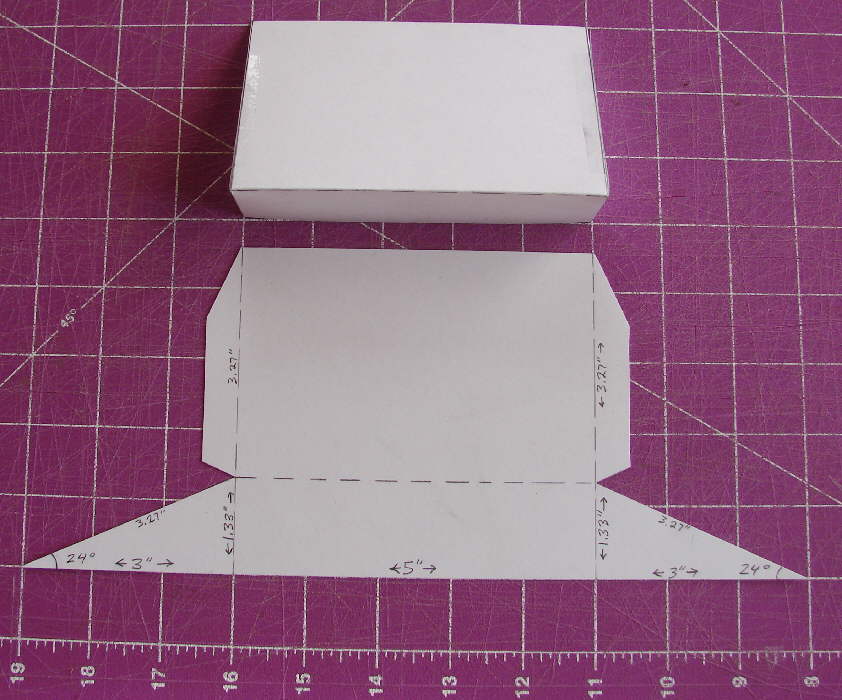
Above: 24 degree dihedral gluing support folded from a sheet of card stock, then taped into the wedge shape 24 degree dihedral gluing support folded from a sheet of card stock, then taped into the wedge shape

Above: 24 degree dihedral gluing wedge in place, ready for gluing dohedral joint- just keep in place while hot melt glue sets up. 24 degree dihedral gluing wedge in place, ready for gluing dihedral joint- just keep in place while hot melt glue sets up.

Above: 6mm Motor mount for 10 gram or 17 gram motors, installed on 1/16" birch ply plate, 5 degree downthrust. Two 1.5mm CF pins , top & bottom, glue back into wing front spar pair & through foam with CyA. Hot Melt fillets finish mount.

On the 16 gram motor, I'm flying a GWS 8x4.3 SF prop that is trimmed to 7.6" and balanced. I'm looking forward to digging out an APC 8x3.8 Slowflier prop to fly on this girl- it should be about perfect.
Note- I balance GWS slowflier props by adding clear scotch 'multipurpose' tape to the back side of the light blade's tip; I add it progressively until the prop balances, starting at the tip and laying 1/2" strips smoothly , edge to edge, working my way in along the blade as necessary.
The wing's 24 degree dihedral angle seems perfect, and the ~5 degree down-thrust angle also seels about perfect across the full speed range. I can tell that the battery wants to be directly on the centerline... with it velcro mounted, I needed a bit of right trim to counteract the slightly off-center weight. Once I decide exactly where I want to locate it, I'll cut in the battery compatrment and trim a bit of excess EPP on this girl's belly. (After that, I'll decide whether a couple of degrees of right thrust will also further balance out the FLIRT's performance.
Materials needed / used:
6mm thick EPP foam for the main wing & upper fuselage; 9mm EPP for the under-fuselage optional.(you can order fron RCFoam.com)
1mm diameter CF rods (also available from RCFoam.com) for spars and for stiffening of the EPP foam in the rudder and elevator (and in the vertical stabilizer if needed)
1.5mm diameter CF rods (also available from RCFoam.com) for pushrods; also used glued through motor mount plate into foam to secure the motor mount
2mm diameter C.F. rod for the final landing gear axle; 1.5mm CF rod can be used for the down legs for that gear
Kevlar thread (or nylon thread) can be used to wrap the joints on the landing gear, then coat with thin CyA glue.
Scotch cross-filament nylon filament tape (Available from Offoce Depot, or Hobby People.net)
10 gram Brushless motor from Lazertoyz.com; 10 Amp Turnigy Plush ESC; 2S 460 mAH LiPo Batteries [or 2S 360 mAH for indoor / lighter slow flying] (HobbyCity.com, Zazertoyz.com, etc.)
Motor mounting: I used a modest sized piece of 1/16" birch plywood. The firewall mount for either the 10 or 17 gram motore was mounted with three #1 x 1/4" sheet metal screws. three pins made from 1.5mm CF rod run through this plate & back into the foam
Micro receiver and ~5 gram or less servos (I used Vigor 4.4 g servos from HobbyCity.com; their HXT500 servos might also do OK)
Music wire: for landing gear for mono-ski or mono-wheel setup, I used .050 wire; for pushrod ends, I used .032 music wire.
Propellers: GWS EP-6030
There are plans and discussion on building a similar design, the 'Nutball" on the Scratchbuilt Foamies section of RCGroups, so you can refer to that source for variations and build tips as well as more diagrams. I haven't thought that it really is necessary to draw 'plans' for the FLIRT-s main disk wing- it's a simple ~17" diameter circle laid out on EPP foam to start. I mark the center point of a sheet of foam where install a center pin in my sheet of foam extending through into a solid backing. I then use either a piece of string, fishing line, or light wire with a loop on either end that is the right length, and draw out the circle with a fine-tipped sharpie marker.
After you have that, mark out a center line where the upper fuselage willbe mounted, and mark out the 4" maximum width side sections. These are cut away with a beveled cut that is angled to the outside; the idea is to have the pieces match up when they are positioned together & glued together. The elevator is marked out at a maximum depth of 2-5/8" at it's center, and cut away with a ~45 degree cut; a wedge of material is removed so the elevator wil have plenty of clearance for movement at the hinge line. I trim back the ends slightly so there will not be any contact with the wing tip panels when it's all assembled. I'll then hinge the elevator in place right away with Scotch Extreme bi-directional nylon filament tape before going on with the build. This tape bonds directly to bare EPP foam very well. I use a 1/2" wide piece on the top surface, then install other narrow strips only on the underside on the outer corners and in the area where the control horn will be installed later.
Next, I prefer to install the four 1mm CF rod stiffeners, placed as shown in the photos on the top & bottom in two opposing pairs before gluing on the wing tip panels the two cut-away side panels are then simply flipped over so the bevels match, and glued in place using the 24 degree bevel support shown in the photos above. You can use a straightedge and sharp razor knife to cut shallow slits into the EPP for these 1mm CF rods; optionally, an adjustable temperature soldering iron with a fine tip can be used to melt a shallow groove into the surface of the foam where the rod will be glued in place. I place a wheel colar on the soldering iron tip to control the depth of slot which I melt in the foam, letting it ride along the top of my metal straightedge. If you use this technique, do some testing on scrap material to get the temperature set right & get the feel of how the process works.
The FLIRT varies substantially from the basic 'nutball' design in that it has a full length fuselage on both the top and the bottom. This offers some stiffness to the airframe, while also providing good stability without limiting the FLIRT's ability to perform radical aerobatic maneuvers with larger control surface movements. Below is a photo of the pattern for the upper fuselage & lower fuselage pieces as I cut them from 9mm thick EPP; they are laid out on a 1" grid cutting mat. Exact matching of this profile is not critical; this will give anyone who wants to build their own 'FLIRT" an idea of what works.
UPDATE: (I've actually later trimmed away some of the lower forward fuselage, and I'm mounting the battery on velcro on the right side of the lower fuselage, as shown in the photos below. You can exercise some 'artistic license' here.
For more easily balancing the aircraft with a light battery like the 2S 360 Rhino pack, it would be better to install the servos farther forward than where I installed mine; refer to the photos.

The FLIRT was first built with the mono-ski under the front, and tall tail skids under the rear. Later, for bare-ground flying, I had removed the mono-ski and installed a 1/16" music wire single leg landing gear under the front. With either mono-ski or mono-wheel, I found that the Flirt could 'tip over' to either front corner, left or right, when turning sharply on takeoffs or landings. So I decided to install a lightweight two wheel front landing gear and fly the Flirt this way for a while.
I decided to use a 6" length of 2mm diameter solid C.F. rod for the main axle, and installed another 4" long piece of that material on the wing's top surface where the gear down-legs / struts get installed into the foam. I used two 6-1/4" lengths of 1.5mm C.F. rod for the down legs; (2mm could also have been used for these struts.). I wanted the gear tall enough to give clearance for a longer prop if I switched back to the 16 gram motor, and tall enough to allow flying with a pair of lightweight skis instead of wheels later, when the snow returns to the high country. Having good clearance between the snow & the prop is always a happy thing. I used a TLAR approach, using hot melt glue to install the C.F. parts. I used some Kevlar thread (bought in the fly tying section of a large sporting goods store) to wrap the C.F joints where they cross, with thin CyA glue to quickly lock the thread in place. Since the Flirt only weighs 3-3/4 ounces when ready to fly, it doesn't require a beefier L.G. setup; I expect it'll do it's jobe adequately.
I trimmed down the rear tailskids from their origional taller profile while I was at it, and then aded a narrow strip of Scotch Extreme bi-directional nylon filament tape on the lower surfaces.
I also wanted to balance the Flirt while carrying the lighter weight 2S 360 Rhino battery packs, so I added velcro on the forward end of the under-fuselage on the right side. The narrow 2S 360 battery just fits in on a valcro patch just above the landing gear down-leg / strut, and the aircraft balances at the 25% mark with the light battery mounted all the way forward.
I installed light weight 2" foam wheels which already had an axle hole to fit the 2mm CF rod; I used ~1/4" long sections of stripped wire insulation as wheel keepers.
The landing gear setup works! I did a couple of takeoffs & landings on the road at the end of my driveway with the new setup, even though the gusty winds were building as a storm was moving in. I'll fly it more another day.


For more stable forward flight & high speed flying, the FLIRT likes the balance set a bit farther forward, no more than 1/4 of the way back from the leading edge of the wing to the trailing edge of the elevator; on the ~17" FLIRT, that's 4-1/4" back from the wing's leading edge. For prop hanging & nose-high harrier-type slow flying, the balance can be shifted back a bit more by moving the battery back a bit. For more forgiving handling, shifting the balance forward a bit from the 25% point will definitely make a difference in taming the control response.