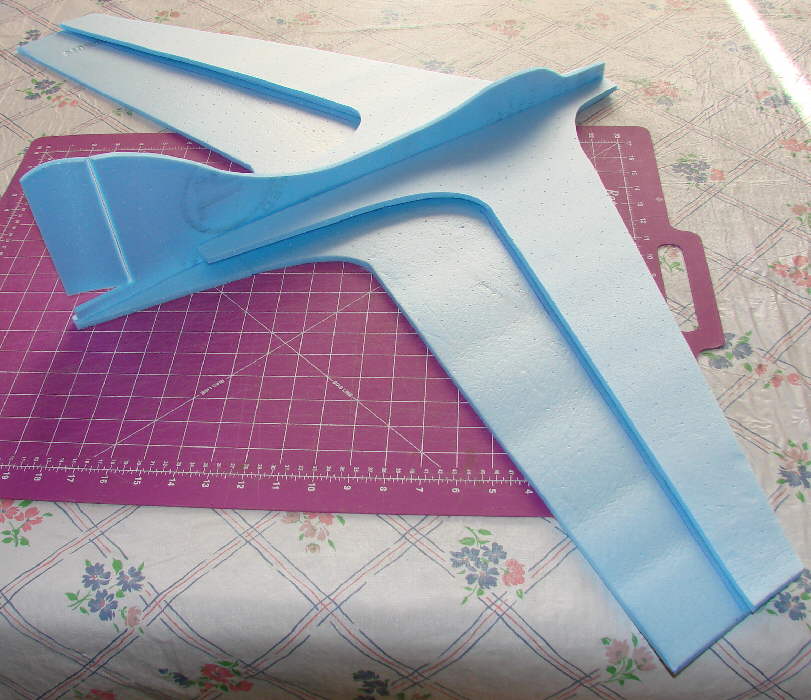
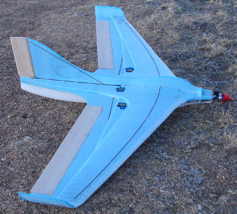
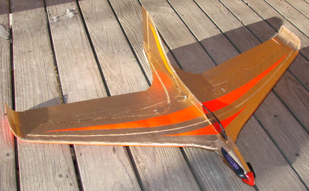
Here's the new Me163 variant - the "ME163-e"; this is my designation for an electric powered variant that has been morphed to use an 8" or 9" folding prop on an extended slim nose. It's at 39-3/4" wingspan as shown in these photos, with an overall length of 26-1/4". The 'e' is for electric, eliptical, and efficient.
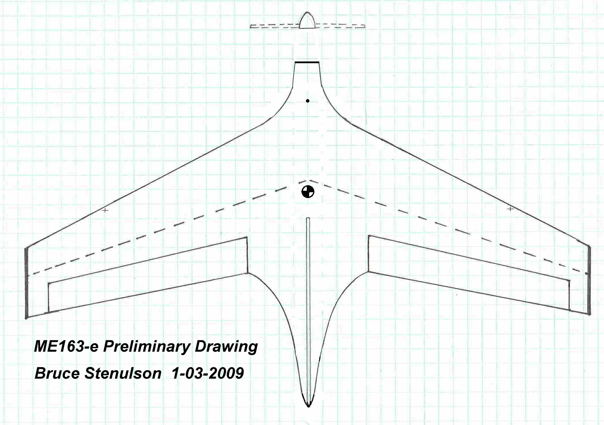
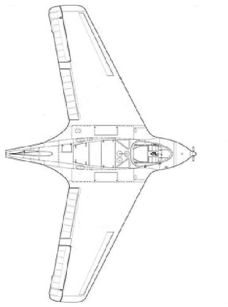
The image below is the top view of the Me163b; I used this to lay out the main wing panel of my Me163-e
The origional 1940's Me163b was a rocket powered fighter; it had less than ten minutes of fuel capacity, after which it would glide in for a landing. (It was one of the early 'Climb-And-Glide' aircraft.)
DAW produced an all-EPP slope combat version ; they trimmed domn the scale fuaselage dramaticly to minimize drag. I'm not concerned with imitating any 'scale' side profile appearance; the origional Me163b had a very deep fuselage profile that does not serve my purposes. What I'm designing for is a minimal drag airframe that will perform well in both 'climb-n-glide' thermal performance, as well as for powered slope flying and warmliner aerobatics.
If this build project looks a bit more complex than many 'quickie' foamy builds, I'll say that the build is still fairly simple. There are just three extra airfoil-shaping strips installed between the lower and upper wing surfaces on each half of the wing, and a fair amount of foam shaping involved.
The concept is to end up with an aircraft that handles solidly and smoothly at high speeds under power, and that also has very efficient glide capability when the power is shut down in thermal hunting conditions. I also am looking to end up with an aircraft design that can comfortably fly in slope winds up in the 25 MPH to 30 MPH range, without needing to ballast heavily to achieve good forward speed and penetration. This more elaborate wing airfoil shaping should help to accomplish this design goal.
I'm not looking for a light air floater that can't penetrate slope winds... I have some of that type of aircraft in the hanger already... so while my build will use light weight materials, I'm focused on airframe strength and rigidity, along with minimizing drag.
I'll implement a top KF step at 50% of chord on a ~8% max thickness wing; I'll extensively carve / sand / shape and heat-form the leading and trailing edges to an airfoil profile, as I did on the DANCER wing which has worked so well as far as glide efficiency and wind penetration while slope soaring.
It's stated by airfoil design experts that 50% of a wing's lift is generated by the shape of the forward 25% of the airfoil. That's the motivating concept for adding the extra airfoil-shaping structure elements within the front half of the wing, and investing the time in all of the shaping.
AIRFOIL PROFILE NOTE: The DAW Me163 EPP slope combat kit used an MH45 airfoil, and flies with the elevons reflexed up at the trailing edges. This is common practice in airfoils used on flying wings and aircraft without horizontal stabilizers. The wing airfoil profile I'm building is thinner, closer to the MH32.
Here is a drawing of a the KF variant-modified MH32 airfoil I've designed, which is being used on the ME163-e; it uses three tapered strips of Bluecor to form the airfoil shape throughout the tapered wing's span. Simple to build, but it results in a strong wing structure.

In developing the Dancer wing, I found that when a KF step was placed at 50% of chord on top, that the center of lift was shifted back to 38% to 40% of chord; (in comparison, a flat plate wing generally has it's effective center of lift at ~30% of chord.) This is one of the most noticable affects of adding the KF step on top at 50% of chord.
If you have time to visit the DANCER web page, you'll see more of this discussion, and the concept that A KF step is not an airfoil, per se, but only one aerodynamic feature of an airfoil. Adding such a structural element to a flat plate wing just makes it a modified flat plate wing.... Adding a top step at 50% to an RG14 or RG15 or MH32 Airfoil, on the other hand, can result in a very high efficiency glider wing- one that actually has a bit MORE forward speed under power, and appearantly LESS drag.
Dancer KF Variant wings and construction details and photos are found on the DANCER page here: http://www.stenulson.net/rcflight/dancer.htm
But Ahhh, here's the catch... for optimum power-off glide efficiency and slope wind penetration at modest wing loadings, you have to actually shape the forward 30% section of the airfoil to get the lift generation capabilities, and you have to shape and thin the aft 20% of the aiorfoil for minimum drag and high efficiency gliding performance.
I'm looking to build my first prototype of the ME163-e into another high efficiency glider design, as well as for slope soaring in winds up to ~25-30 MPH, so I'm focusing the wing's airfoil shaping for those tasks. Aileron area, using 2" wide tapered balsa aileron stock, is very adequate for the roll rate I'd like to have available. The same material is used for the rudder.
I'm also implementing the eliptical upswept wingtips that were built onto the Dancer wings; they actually increase the wing's lift and have definite stabilizing effects while further reducing drag.
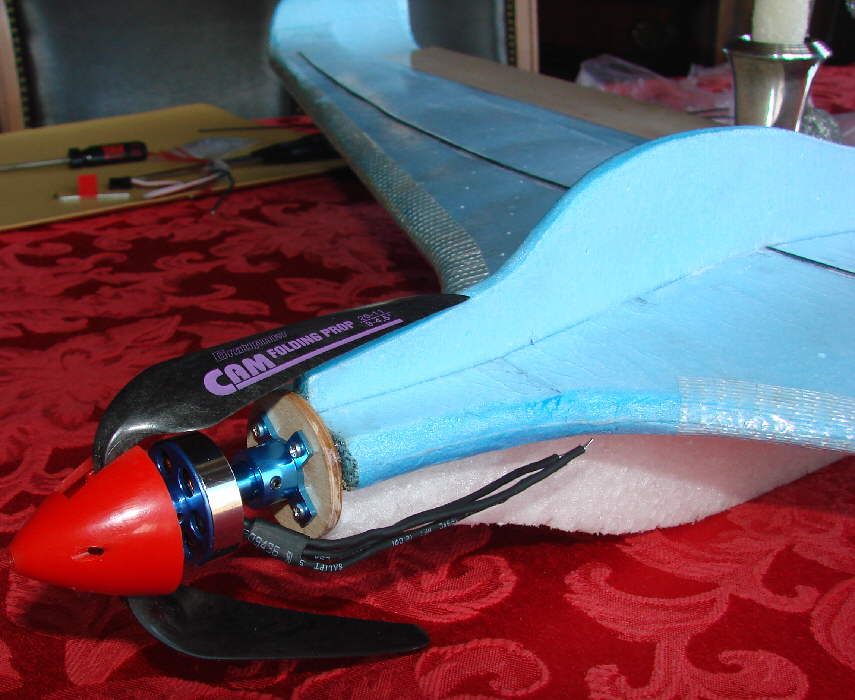
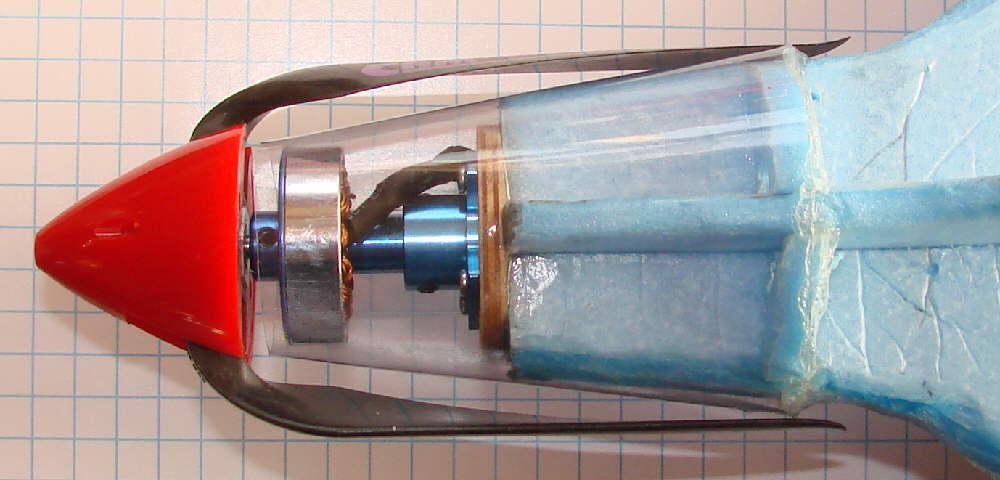
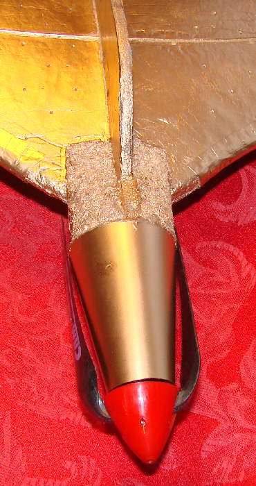
I have decided to start flying this Komet with a 24 gram 2712 motor, 1500 Kv, turning 9x4.5 Graupner CAM folding prop blades on a narrow spinner. The nose has just enough length of the slim area behind the motor for the prop blades to fold in cleanly. (Adding the tapered conical motor cowling will be one of the last steps in the trim-out.) This firewall mount approach allows a variety of motors & props to be used.
I added another 1.5" of span at each wingtip, beyond the 39" 'scale' profile shown in the preliminary plan, so that I have enough wingtip material to implement the eliptical upswept wingtips in the outer ~3" of material on each wing tip.

(above:) To start the build, once the rough plan was drawn on the graph paper, I started marking directly on a sheet of Bluecor PP foam. I cut the main wing panel foam, then cut out the two upper layer foam sections and the upper fuselage section.
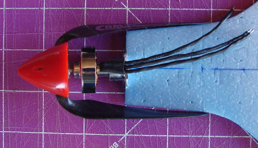
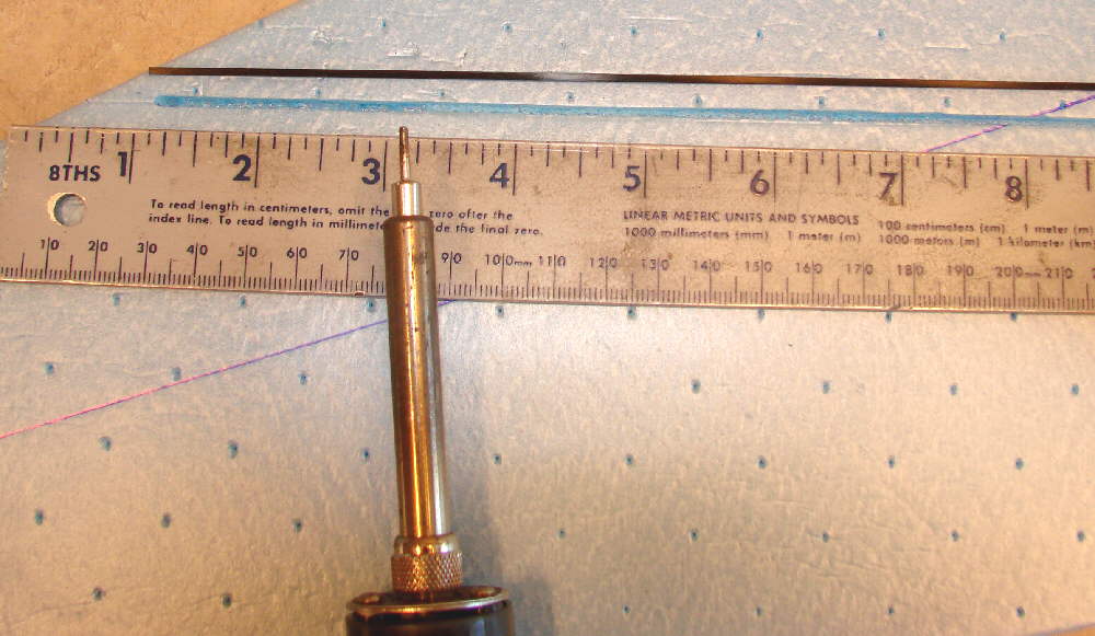
Above: The folding prop blades only need a modest amount of slim nose against which to fold. These are 9x4.5 blades.
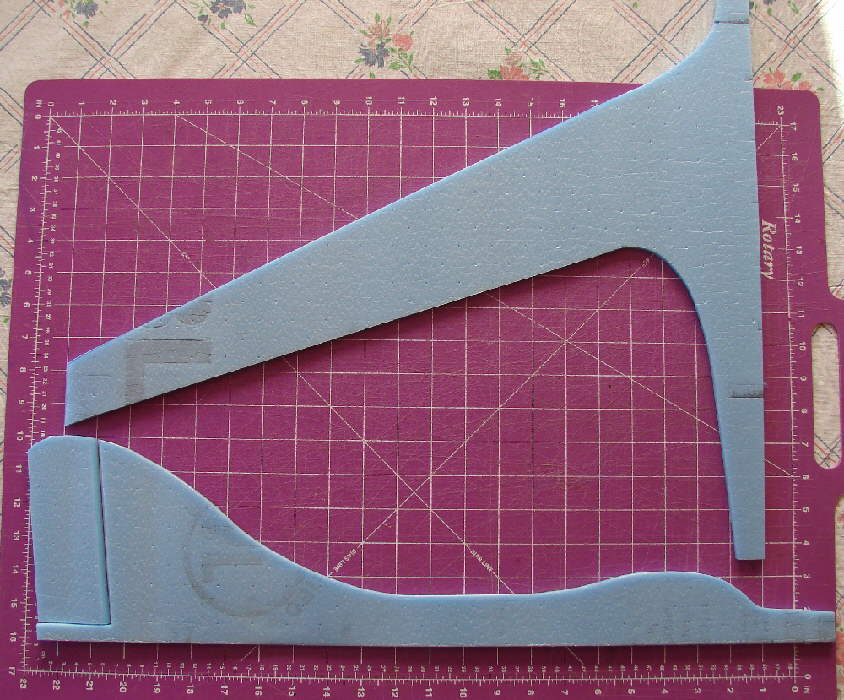
Above: Wing upper panels, extending back to the KF step at 50% of total chord at the wing root, and back to 40% of chord at the wing tips, are laid out and cut.
The upper fuselage on this first prototype will be built from a single layer of Bluecor PP. I'll build an EPP lower fuselage for landing resiliency / durability, which will also to enclose and protect the electronics and flight battery.
Above- test-fitting the upper panels
Below:
The slots for the lower panel spars are made with an adjustable temperature soldering iron set down to about 300 to 325 degrees F. These CF rod spars are inset flush with the surface, directly above & below each other.
(Above:) Spar structures: Someone asked about spar structures; they are always important. The lower wing panel has a pair of CF rod spars, top & bottom, inset into snug fitting grooves that were melted in with a variable temperature soldering iron; there's a 1mm CF rod flush with the bottom surface, and a 1.5mm CF rod set flush with the top surface of the lower wing panel, which run across span-wise about at the center of lift of this wing. These act sorta like the caps on an I-beam, as neither can stretch or compress.
That's only the first stage of the spar structure; another set of 1mm CF rod spars will be added, surface-mounted, once the wing structure build is more complete.
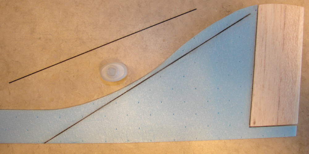
(Above:) There are also a pair of 1mm CF rod stiffeners inset into either side of the vertical stabilizer's leading edge for stiffness. The soldering iron was used again to make the shallow channels for these stiffenwers, These are glued in place with foam-safe CA glue. It's easiest to install these before the upper fuselage is glued to the main lower wing panel.
This photo also shows the 1/4" x 2" balsa rudder that has been cut to fit; I actually extended the trailing edge a bit more with some 3/32" sheet balsa . The balsa of the rudder was then sanded to a very thin trailing edge to minimize drag, & also matched to the 5mm thickness of the Bluecor vertical stabilizer at the forward edge. I covered the bare wood with thin Doculam film before tape-hinging it in place.
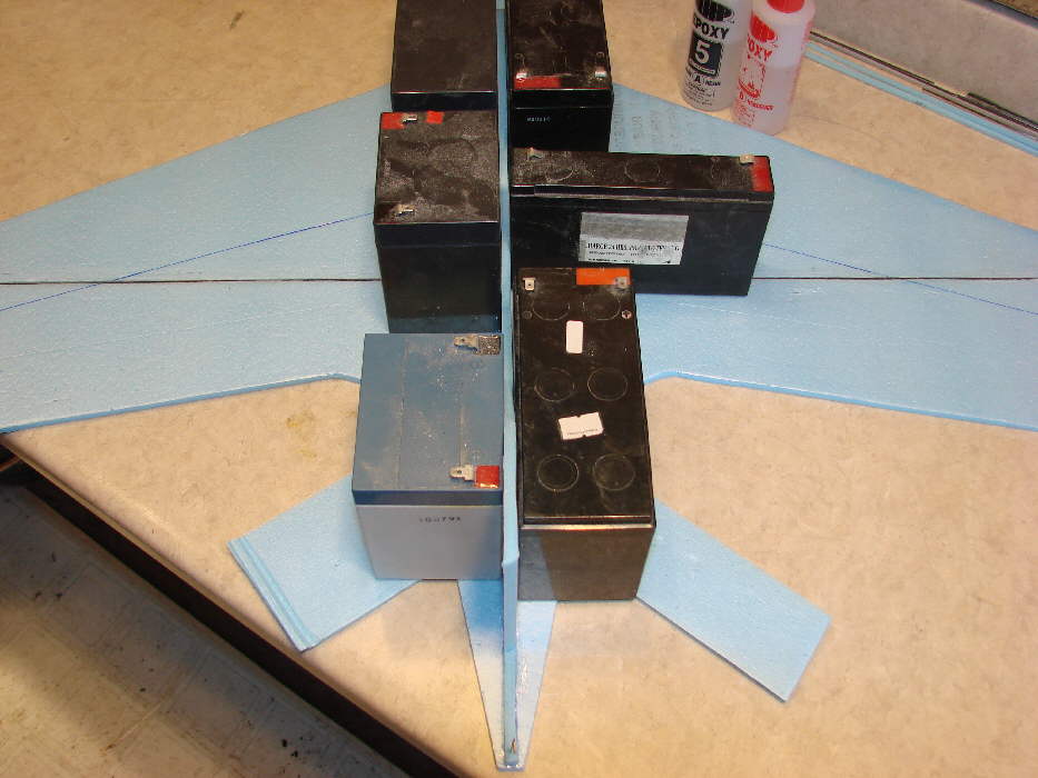
Above: The upper fuselage is being epoxied in place, held in position by my collection of old gel cell batteries.
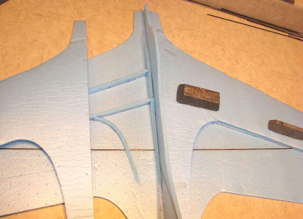
(above:) The wing's top panels have been shaped by hand- rolling over a ~4" diameter heavy cardboard shipping tube. They are being trial-fit and adjusted to match the lower panel and inner structure. In the photo you can also see that some of the inner core structure is glued in place on the lower wing panel. These are simply tapered strips of Bluecor, easy to cut. Mounting these bluecor strips to the lower wing panel is the one place where I used hot melt glue in the construction of the Me163-e; I used either 5 minbute epoxy or foam safe CA glue for all other parts of the build.
Below: After the main cross-span wing spars were inset & glued in place, the outer 3" of the main wing panels have been curved and heat-formed into the eliptical upsweep; their upper edges (before final shaping) are 1-7/8" above the lower surface of the wing. The foam for the upper wing surface layer have been thinned extensively at the wing tips before it's installed over the lower wing structure.
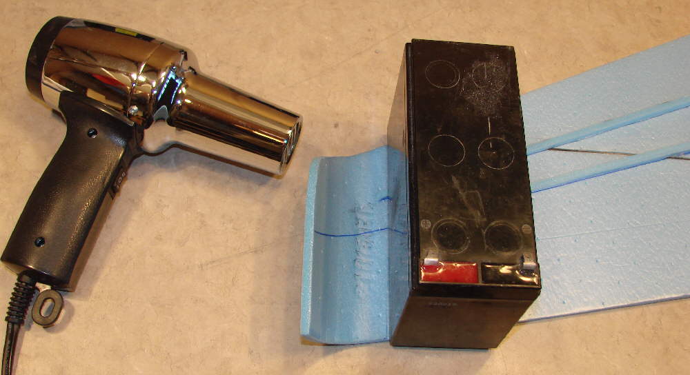
(above:) The wing's outer 3" is rolled up, then heat-formed into the rough eliptical wingtips. Further shaping, thining of edges, and heat-forming will be done later.
Below: This photo shows the inner wing core strips /structure in place, ready for the top wing skins to be sanded to final fit and then glued in place.

(Above) : The 1/4" x 2" tapered balsa elevons have been further sanded and shaped, with some of the upswept trailing edge reflex formed. The trailing edges have been shaped to a very thin edge to minimize drag. They have also been matched to the Bluecor's thickness at the hinge line. The Bluecor of the main wing panel itself has been cut on a ~50 degree bevel; there is no bevel on the balsa elevon itself. Once sanding and shaping was completed, the elevons were also covered with the thin Doculam film. The elevons were then tape-hinged in place with Scotch multi-purpose clear tape; I use 1/2" wide tape on the top surface full-length, then add a full length strip of the 3/4" wide tape on thwe underside of the hinge line. (Be sure to leave a 1/32" gap between the wing and elevon edges when applying the tape hinging, to provide clearance for the tape when the elevon id deflected full down.)
I fabricated a pair of lower height (KFm3 type) 'secondary step' panels from 5mm Bluecor. This type of KFm3 variant wing construction has performed superbly on the Dancer's 9% thick KFm3 variant wing, as far as providing exceptional low speed glide efficiency performance. Only a modest area is filled with this secondary panel on the Me163-e.
Once the rest of the wing structure is completed, another pair of 1mm CF rod spars are mounted, top & bottom, running ~ parallel to the wing's leading edge at ~15% to 20% of chord as shown in the photos. These are actually one piece spar caps that are run through the upper fuselage, and curved into the shape shown. They are placed directly above / below each other in shallow depressions in the foam surface.
These 1mm CF rod spars add further structural strength & stiffness, as well as twist resistance to the wing. These spar cap rods will be only partially inset into the surface, without breaking the surface film on the Bluecor PP; a groove is formed by simply pressing the rod into the foam with firm pressure once it's in place. Then a pin is used to make a series of pinholes through the surface film along the edges of the carbon fiber rod, so that the foam-safe CA glue that is used to glue the spar caps in place can penetrate well into the core of the Bluecor. I then apply a bit of baking soda sparingly on either side of each spar to fill the slight gap and bond them solidly in place.
These spars are then in place to effectively act as a turbulating spar or 'trip strip' at about 15% of the chord on the outer half of the wings, where it is most effective at keeping the boundary layer air turbulated and attached in the forward area of the airfoil's top surface. (The Dancer page has more written on this subject. The KF step does it's magic starting back at 50% of chord.)
So there are a total of 4 spar caps in this wing working together to limit flex in more than one dimension, with minimal total weight. The 1mm CF rods are only .84 each from RCfoam.com, so the cost is modest, and the weight is minimal.
In the photo above, the top surface CF rod spar is being glued into it's depression in the foam with foam safe CA glue.

The photo above shows the bottom surface of the wing after the second eliptically curved spar was set in place; it's directly below the curved spar on the top surface.

Above: top spar in place and secondary KFm3 inserts in place, and the carving / sanding / heat shaping of the wing is completed

(above:) Me163-e main wing structure complete; wingtips and wing leading edges are shaped and heat tempered. (I carve away excell foam in places as appropriate with a sharp razor knife before using a covering iron to complete the heat forming / shaping / foam tempering.)
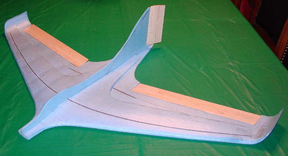
The Me163-e Komet's clean lines, extensive airfoil shaping, and stiff wing structure should penetrate winds well and perform well at high speeds and in heavy slope winds.
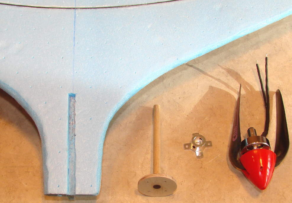
Above: the motor mount is fabricated from a disc of 1/8" birch aircraft plywood, with a 1/4" diameter hardwood dowel glued in a hole in it's center. The channel for mounting this motor mount is made with 1 degree of right thrust, and about 1.7 to 2.0 degrees of down thrust. This motor mount is trhen solidly installed in the wing lower panel with 5 minute epoxy.

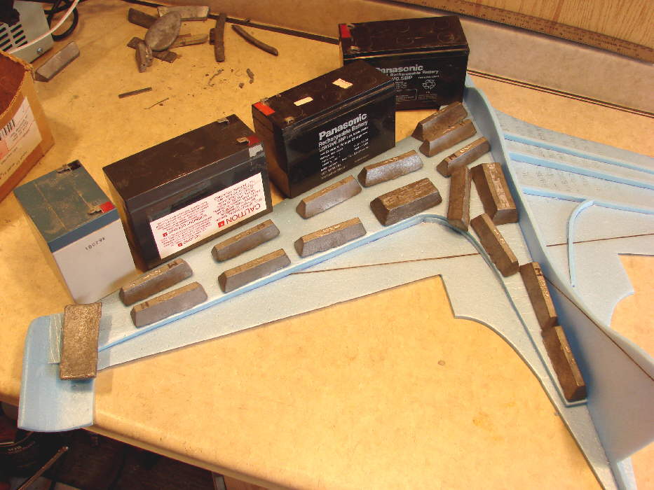
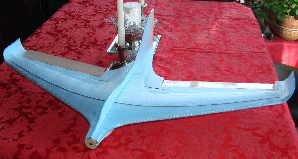
ABove: The EPP foam lower fuselage is being epoxied in place, well weighted down with 1/2 pound lead blocks. This may seem to be a bit larger lower fuselage than might be needed... but until I have verified the final position of the flight battery and cut in it's compartment within the foam, I want to keep the extra foam. I'll then trim, carve, sand, and cover the final shape of the lower fuselage with either trim tape or Doculam film.

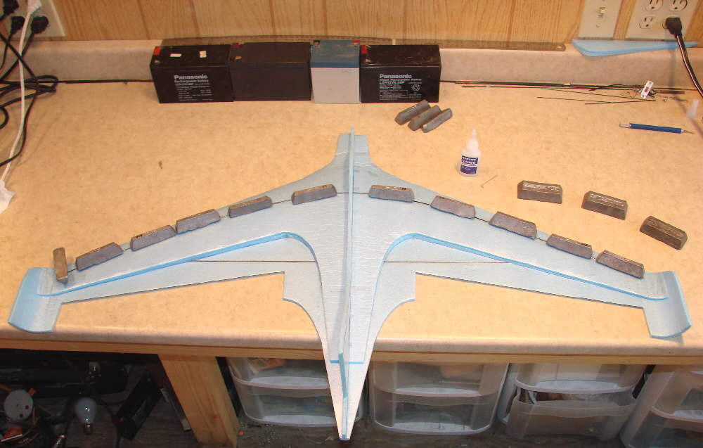
Above: some lead is temporarily taped in place, ready for test glides to establish the starting balance point of this particular wing. The elevons were taped in place with their top surface flush with the upper surface of the lower wing panel; the rudder was also taped in place. I actually taped on about 4 ounces of lead, then adjusted the positioning of some of it until the glide was smooth with no indication of either stalling / porpoising, or diving. I then marked this point as the balance point to use for first flights. Final balance adjustment will be accomplished by shifting the position of the flight battery.
A 1" wide strip of Scotch Extreme cross-weave nylon filament tape is now applied to the leading edge of the wing.
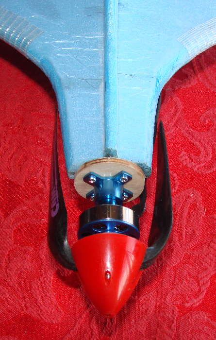
Above & below: the motor is now mounted in the motor mount on the firewall, with the folding prop temporarily slid in place. Some foam filler blocks will be contoured to fill the nose behind the firewall. Then flat polycarbonate plastic sheet (from a two litre soda bottle) will be formed into a conical motor fareing cowl and taped in place.

Above: The rudder servo is an HXT500 '5 gram' servo; I use a length of 1.5mm CF rod for the linkage with 1/32" music wire ends secured in place with heat shrink and CA glue. Elevon servos are HXT900 9 gram servos; as placed laid flat, their cases are flush with the lower surface of the wing, and flush with the top of the secondary KFm3 step pannels.
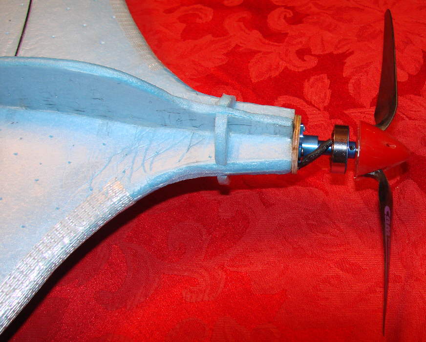
Above: four pieces of Bluecor foam wer shaped and glued in place where the folding propeller blades come in around the forward fuselage. This not only will keep the blades from hanging up on the initial test flight, but forms some of the support structure for the conical motor cowl / fareing which will be added later.

The elevon servo is close-coupled to the elevon with 1/32" music wire; a short section of snug fitting wire insulation forms the linkage keeper at the elevon control horn. The Corona 4 channel synthesized receiver is temporarily surface-mounted against the EPP foam lower fuselage; it will be inset flush with the surface when final setup is complete.

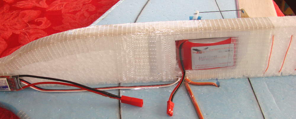
Above: Motor leads were routed through a close fitting cutout through the firewall before being soldered to the TURNIGY Plush 10A ESC. With the electronic components used and their positioning, the balance without the flight battery in place is very close to the ideal balance point. This allows placing the flight battery close to the balance point, keeping the mass centered, and allows use of various sized batteries in that position without changing the balance of the aircraft. Once final balancing range is verified, a battery compartment will be cut into the EPP foam, so that the flight battery will be inside, out of the cold winter air, protected during landings, and not causing any drag.
Here's a photo of the Komet just before the first test flight- just after sunset on 1-4-2009, with the temperature at zero degrees F. The battery was velcro mounted & thoroughly chilled before the flight started... and my fingers were the same, so the first flight was very successful, rather brief, and very gratiftying! I had set up Aileron differential of 25%, and limited total rudder travel to ~5/8" in each direction. The ESC had the brake set ON so the folding prop would fold in cleanly when power was turned off; this worked well during the test flight.
The M163-e Komet handled very smoothly and cleanly. It climbed out well under power - especially considering how cold the battery was! I'd set the balance a bit forward from the point identified in the earlier test glide as the ideal glide efficiency balance point, and it handled well with excellent stability. Aileron response on low rates is good, producing a smooth roll at a moderate rate. It loops well, and flies like it's 'on rails'- an attribute of the eliptical upswept wing tips. Rudder response is also clean and predictable.
The eliptical upswept wingtips also allow the aircraft to fly as if the wing has dihedral- even though the main wing is built totally flat. So it's not as 'busy' to fly as a flat winged aircraft would be. All in all, ait VERY satisfying first test flight in frigid flying conditions! Now to finish out the build!
I'll fly more on another warmer day with better light, and work on shifting the balance back in stages gradually to identify the best balance position for high efficiency thermal gliding.
Above: Here is the patern I developed to make the rolled sheet plastic cowl for the ME163-e Komet. It overlaps about 5/8" when rolled to fit my installation, and is taped with Scotch multi-purpose transparent tape. I trmmed it & fit it so it was not touching the outrunner motor, then locked it in position with hot melt glue.
Above: Here's the resulting installation, which cleans up the airflow ovwer the front of the nose. (I may do some aerodynamic filling behind the back edge of the cowl.) There are ventilation holles in the four bluecor rear formers to allow cooling air to circulate through the motor and past the ESC.
Above: A receiver is now mounted within the wing structure on the bottom side, flush with the wing's lower surface, and held in place with clear tape. Servo wires are also taped down for minimum drag. After noting irregularities in the servo drive, chattering in the servos, and jurky servo operation, this receiver was removed, and a Corona RS610 receiver was installed in it's place. Servo operation is now quiet and smooth.
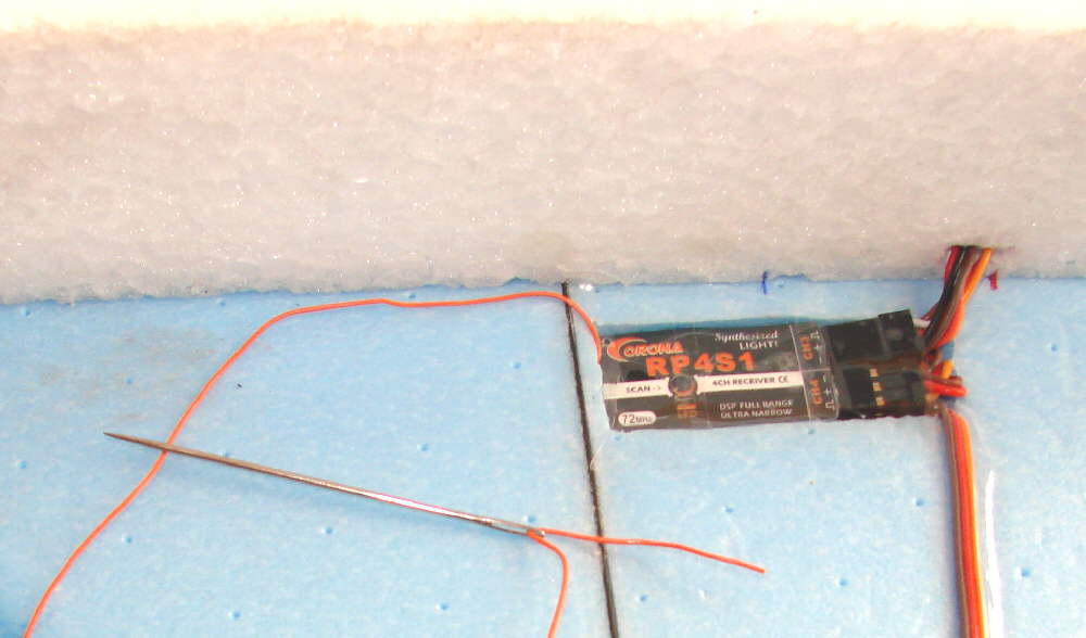
The next question was, what to do with a ~40" long antenna wire? I did not want to run it close to the 1 meter long CF rods in the wing- (they may be able to absorb and mask the radio receiver's signal, reducing range dramaticly, being very closely matched to the length of the antenna.) I finally decided to do a variation of what I've done on combat EPP slope ships as well as on the EPP Beagles. S I got out a large sailmaker's needle!

Above: This is the result of the needle work, sewing the antenna wire through the EPP lower fuselage. The tail end was laid back close to the rear end of the fuselage after the majority of the length was installed in the big rectangular coils shown in this photo. I expect it will work well for this design; I'll let you know the resultas of the range check and flight check before too long.
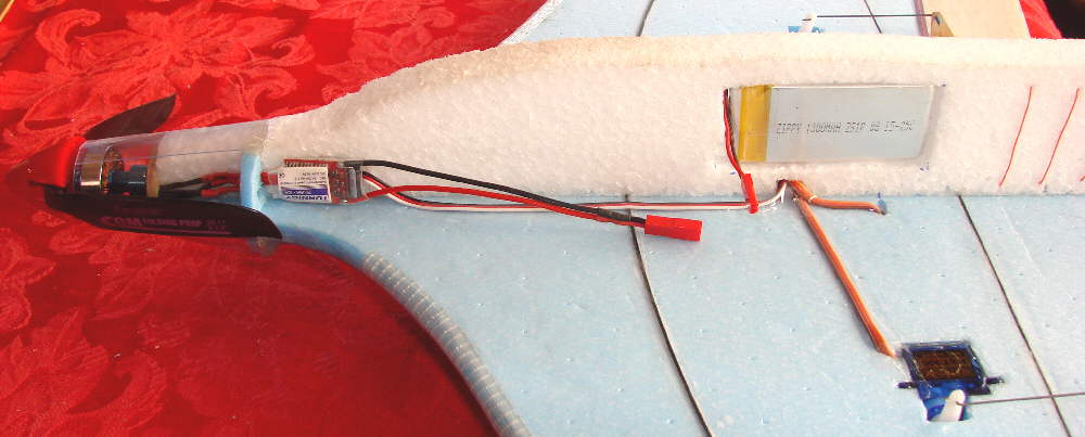
Above: This shows the battery compartment cutout, positioned to carry a 2S 1300 mAH Zippy battery pack so that the aircraft is balanced at the desired point.
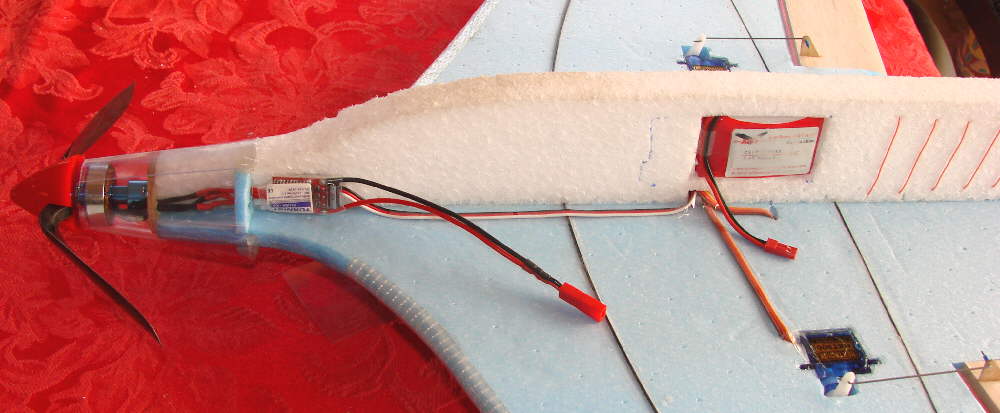
Above: This shows the 2S 900 mAH battery pack in the same cutout, with a filler in the forward end to position this smaller battery correctly for proper balance.
Above: All of the taping around the battery carrying compartment is completed, and the two clear plastic covers are taped in place. I use Scotch 'Extreme' cross-weave nylon filament tape, as it bonds well to bare EPP, and is incredibly tough. The lower contact surface of the entire EPP lower fuselage also has been reinforced with a layer of this tape, to prepare the -e Komet for rough field landings.
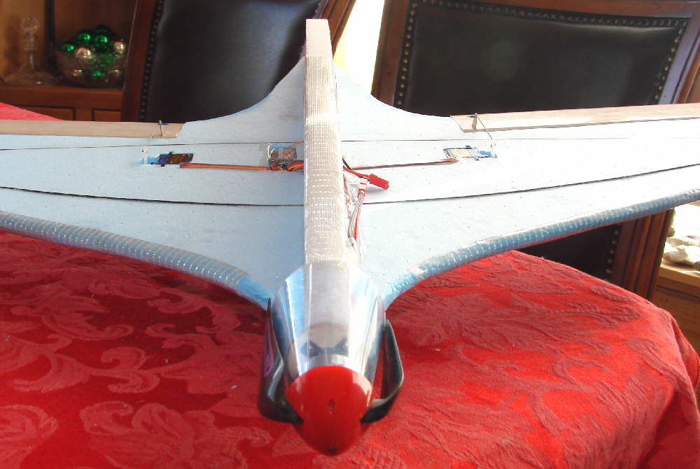
Above: This is the nose-on view down the underside opf my Komet, showing how everything is inset flush with the surfaces as much as possible.
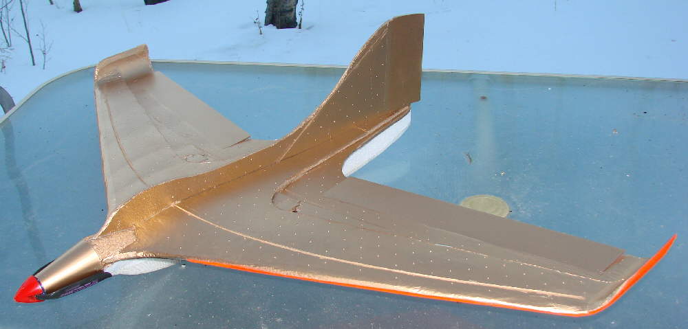
Above: I did some of the dress-up work on this Komet. The photos show the progress so far. I also added the EPP streamlining faring pieces just off the rear edge of the motor cowl. All three colors of spray paint are Pactra 'Odds-N-Ends' spray paint.Top surface now has a base coat of metallic gold, ready for trim.
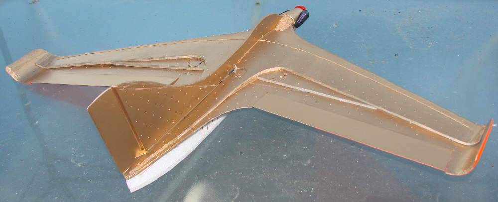
Above: KFm3v wing structure elements are very obvious from this angle

Above: Bottom of wing painted for high visibility at altitude. Lower fuselage remains to be trimmed out.
Beauty has it's price... the Komet is a half ounce heavier after the last farings were mounted and the paint went on.
This is not necessarily a bad thing at all... having enough weight to penetrate winds while slope flying, and being able to drop it's nose a bit and really cover ground while thermal hunting was all part of what I wanted to be able to do with this new variant on the Komet silhouette when the power was shut down. Wing loading has just made it over 5 ounces per square foot... still very light for heavier wind slope flying.
GPW, on RC Groups, commented: "It's a real Beauty...!!! I see you used all the tricks too!!! Good Flying to ya'!!!!"
My reply: Thanks for the kind words!! Yes, I used all of the tricks.... Lousey weather for flying means good weather for designing and building! I wanted to see what's possible when all of the details are working together on this swept wing design.
I truely love the climb-and-glide thermal flying, as well as the powered slope thermal flying early on the days before the winds build up strong enough to keep the slope combat ships in action. Glide efficiency and wind penetration capability are key design criteria for this.
Throwing in the three strips of bluecor on either side of center to bring the top surface of the wing up to the airfoil contour was really simple & very effective- a few straight cuts on scrap material & hot melt glue to quickly anchor them into place.
Yes, I used ~$4.00 worth of 1mm CF rods for spars & stiffeners... I'm calling it a 'good trade' for the rigidity of the wing that resulted.
The leading edge & trailing edge sculpturing is simply a labor of love, knowing what's possible on a clean wind ship when these details are optimized. That's just me..... given enough lousey weather, I'm inclined to spend my time on all of the 'tricks'!
I'm very happy with the results; although the test flight was brief, in zero degree still air with a shakey radio receiver, I saw enough of the glide efficiency and handling potential to be very satisfied.
The low speed landing approach glide, and being able to pull the nose up into a mush at a moderate walking speed just prior to touching down without any sign of a stall, is also gratifying; the KFm3v implementation and the eliptical upswept wingtips were intended to work this way, while actually *Reducing* drag... it's really neat to see it in action!
I did remove the Corona RP4S1 synthesized receiver... since the problems with them have been going on for over a year now, you might have expected that Corona would have got them 'right' by now... but the servo chatter produced with the one I had initially installed should have been a major wake-up call. Once I installed the RS610 receiver, the servos are beautifully quiet, with nice tight centering and very smooth movement- (the RP4S1 was jerky and caused the servos to make some ugly sounds!) So this change is just what I like to see!!
My thanks again to AC for calling my attention to this. After the time I've invested in this new Komet prototype, I'd really hate to lose it to a faulty receiver! (And the detail that the RP4S1 receiver can fail while in the air and keep the motor running in a fly-away doesn't thrill me at all....)
MORE THOUGHTS:
After slamming the synthesized version, I would also like to say that the Corona crystal-type single conversion RS410 and and RS610 receivers have performed as flawlessly for me as the BERGs, and I will continue to buy and fly those specific receivers.
(That dual conversion RD620 in my Varrkain has gotto go though.... the last flight with that receiver was another test for Faith, Hope, & Charity.... NOT fun! )
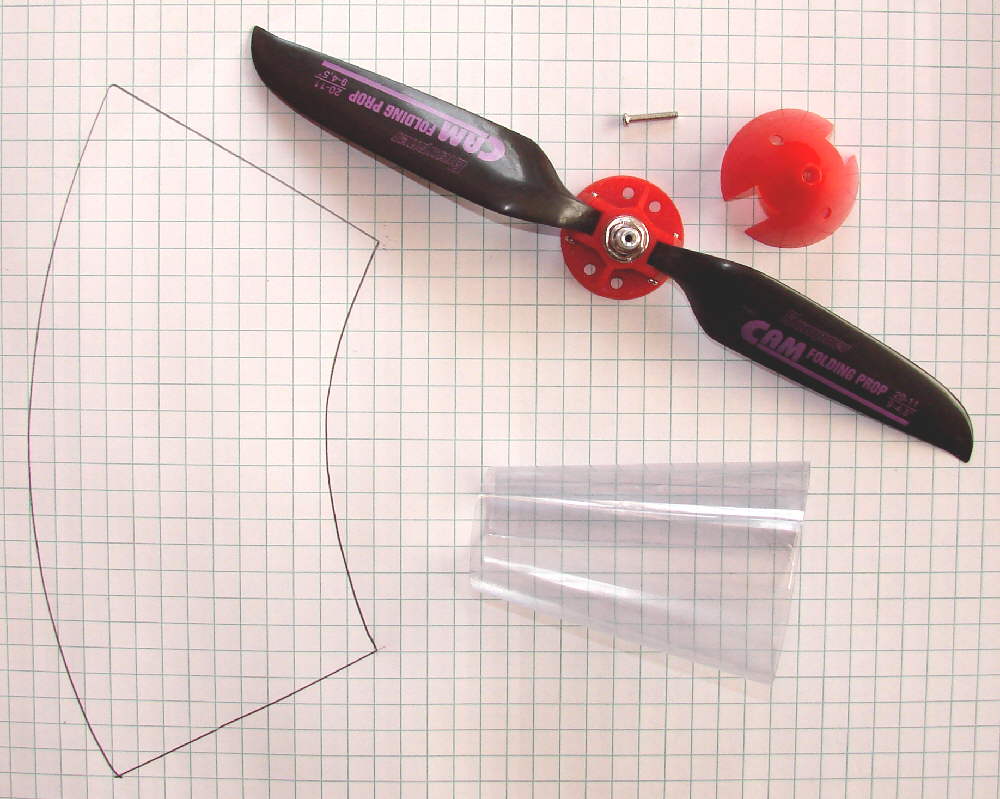
Above: Folding propellers : During my first test flight, I had the impression that the motor really wasn't loaded very heavily. A test with the Wattmeter later confirmed this; the current draw on the 2S 900 ABF pack was only 5.8 Amps. I started thinking about propping up- increasing the blade pitch.
Then I got a bit of a surprise... when I measured the folding prop as it was moyunted together, the blade span was only 7-5/8" .... I had assumed that, since these CAM blades were labeled as 9x4.5, that they would have that span.... not so.
I had a set of CAM 9x6 blades on hand. When mounted, these blades do span 9". These would increase the thrust. When mounted on the aircraft and tested with the 2S 900 ABF pack, the current draw was 7.0 amps. But when tested with the Zippy 2S 1300 pack, the current displayed at 7.8 amps, and the RPMs & thrust were increased noticably. I expect that I'll like the increased performance of the larger battery, despite it's being heavier.
Since these prop blades really did have a full 9" span, they were reaching back along side of the nose another ~3/4"... it was time to do a bit of removal of a bit more foam so that the blades would clear nicely. The photo below shows the result after the paint touch-up.
January 17th, 2009: Flew the Komet today in two different settings- first, I was flying light breezes on the flats a couple of miles from home before noon... Temperature in the low 20s, no thermal activity. It's flying well, and gliding quite cleanly and efficiently.
After flying the 2S packs for a while, I put in a 3S 900 ABF pack. WOW- with 50% more voltage, this Komet kicks butt!! It woke up & started REALLY covering some sky- much stronger vertical climb, faster airspeed, faster roll rate. This is the setup for fun flying, doing the power-on aerobatics in any air. I'll be flying these 3S packs when I feel like simply tearing up the sky! This pack, when installed to the rear of the battery compartment, shifts the balance back about ~1/4" from what's shown on the plans. A bit of the elevon reflex is trimmed out, and the throttle>elevator mix is reduced to +2%. It's definitely flying and gliding cleanly with this pack & balance point.
After taking my wife to lunch, we drove out to Lookout Point. Winds were up at ~18 to 20 MPH with fairly good orientation into the slope- crossing somewhat from the right, but very flyable. The temperature was maybe up to 33 degrees F by this time.
I installed the light 2S 900 ABF pack in the back of the battery compartment & launched into the wind with power on to climb up & out for a few seconds, clear of the scrub aspen just on the crest of the slope. I cut power soon & started cruising the slope- no need for the motor here- The Komet was definitely in it's element!
Even at the light wing loading, the Komet can drop it's nose a bit and move out- it's penetrating the ~20 MPH winds easily and handling the slope flying conditions very well.
With a heavier battery pack (or with a bit of ballast weight added) it will fly faster and penetrate much higher winds effortlessly. The handling is predictable and consistent.... I'm quite happy with the Komet, to say the least.
January 18th, 2009: I want to add some further comments on the glide efficiency and wind penetration capability of this Komet. Even at a wing loading of just under 5 ounces per square foot, this wing glides very well, and is penetrating and handling slope winds up to ~20 MPH so far without any problems.
This is a better performance capability than I had seen in the flatter -built wings with a KF top plate /step, such as my build of the KF Crossbow. While I did a lot of leading edge carving and heat-shaping on that wing, it doesn't penetrate winds as well as I wanted. When the wind speed edges up above ~12 to 14 MPH, my KF Crossbow starts to get blown away on our slopes here in Colorado's high country... it just doesn't have the same penetration and stability in rougher air. It gets really 'busy' flying it. Maybe it has something to do with the 16% lower air density up here, compared to sea level...
So the structured airfoil shaping of the forward half of this MH32/KFm3v wing profile buildout of the Komet has proven it's value. The four 1mm CF rod spar caps have produced a rigidity in the wing that I had hoped for, based on what I've seen in using pairs of them in previous designs. (The Dancer's RG15/KFm3v airfoil performance led the way into the wing airfoil design on this Komet.) And the eliptical upswept wingtips undoubtedly add to stability and allow the outer end of the wing panels to generate more lift, while further minimizing drag... well worth the minor effort of shaping them from my perspective!
The prop brake on the TURNIGY Plush 10A ESC is working great- you can hear it kick in when you chop throttle, and the folding blades fold in quickly & cleanly against the sides of the nose.
The folding prop undoubtedly helps in the glide efficiency department, and in the wind penetration aspect- both essential for light wing loading slope gliding. A fixed prop has a significant amount of drag.
Below are photos of the Komet after the top trim was added.

(Below:) This is the edited version of the first rough plan for a variant of the ME163-e, designed for e-power with an 8x4 to 9x4.5 folding prop. 39" span, 26-1/4" O.A. length, top KF step @ 50%.